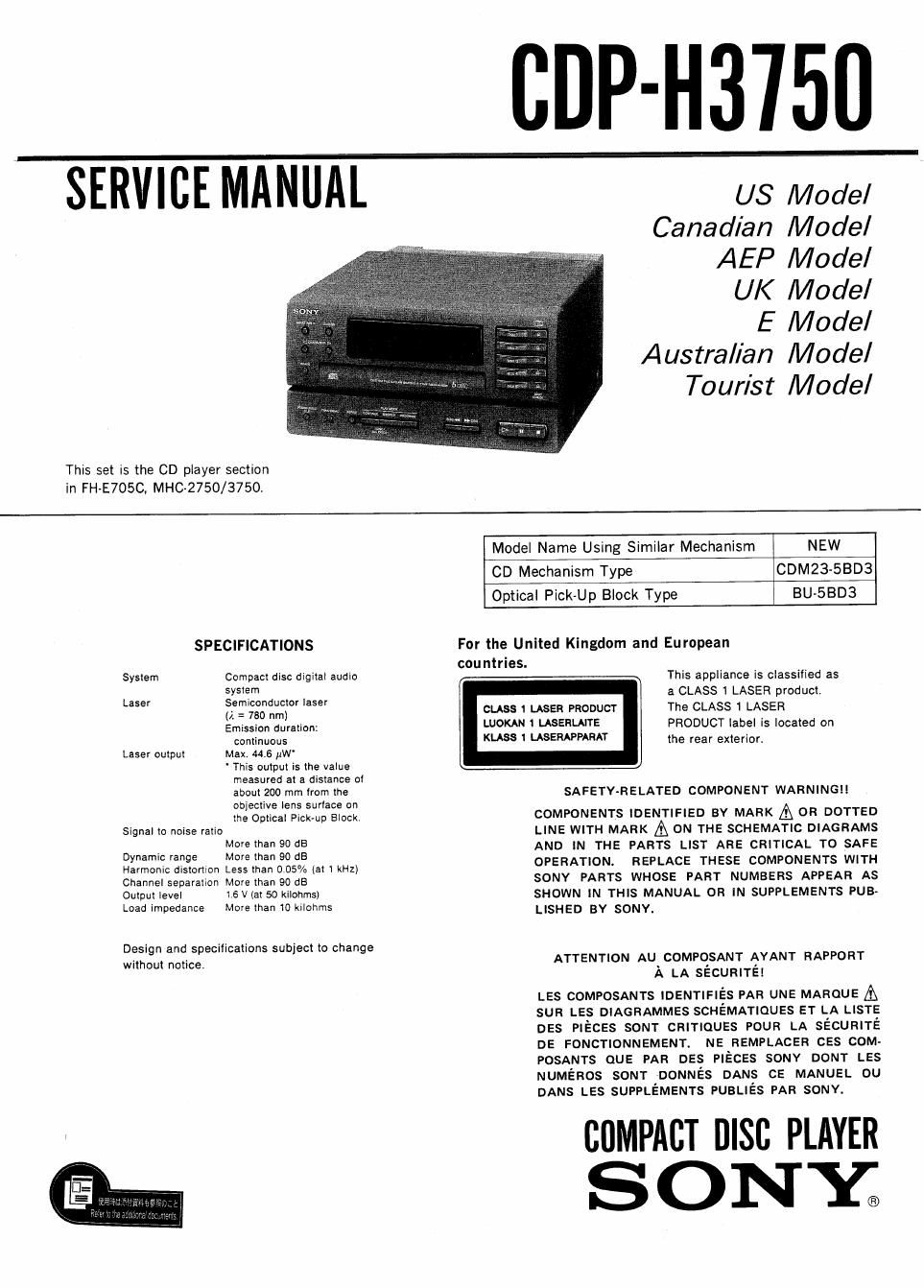
Sony cdp h 3750 service manual

This is the 39 pages manual for sony cdp h 3750 service manual.
Read or download the pdf for free. If you want to contribute, please mail your pdfs to info@audioservicemanuals.com.

Page: 1 / 39
left right
sony cdp h 3750 service manual

Extracted text from sony cdp h 3750 service manual (Ocr-read)


Page 1

CDP-H3'I50

SERVITIEMANUAT U3 Mode,

Canadian Model
AEP Model

UK Model

E Model
Australian Model
Tour/st Model

This set is the CD player section
in FH-E7OSC, MHC-2750/3750.

Model Name Using Simi|ar Mechanism NEW
CD Mechanism Type CDM23-SBD3
Optical Pick-Up Block Type BU-SBD3
SPECIFICATIONS For the United Kingdom and European
countries.
System Compact disc digital audio This appliance is classified as
Laser :fefieignductor laser a CLASS LASER product.
(I: = 750 nm) cuss 1 LASER PRODUCT The CLASS 1 LASER
Emission duration: WOKAN I LASERLMTE PRODUCT label is located on
continuous 531 USERAPPAMT the rear exterior.
Laser output Max 44.6 [lW'

' This output is the value
measured at a distance of

about 200 mm from the SAFETY-RELATED COMPONENT WARNING

objective lens surface on

the Optical Pick-up Block, COMPONENTS IDENTIFIED BY MARK & 0R DOTTED
Signal to noise ratio LINE WITH MARK A ON THE SCHEMATIC DIAGRAMS
Dynamicrange 32:32:38 3: AND in THE PARTS LIST ARE CRITICAL TO SAFE
Harmonic dISIDIItOn Less than 005% (at 1 kHz) OPERATION. REPLACE THESE COMPONENTS WITH
Channelsepmm Magma" 90 GB SONY PARTS WHOSE PART NUMBERS APPEAR As
Output level »5Viat50 kilothI SHOWN IN THIS MANUAL OR IN SUPPLEMENTS PUB-
Load impedance More than 10 kilohms LISHED BY SONY.

Design and specifications subject to change
without notice, ATTENTION AU COMPOSANT AYANT RAPPORT
A LA SECURITEI

LES COMPOSANTS IDENTIFléS PAR UNE MAROUE A
sun LEs DIAGRAMMES scHEMATIouss ET LA LlSTE
DES PIECES som- CRITIQUES POUR LA sEcURiTé
DE FONCTIONNEMENT. NE REMPLACER ces com-
POSANTS QUE PAR DES PIECEs souv DONT LES
NUMERos sou-r DONNEs DANS cE MANUEL ou
DANS LES SUPPLEMENTS PuaLiés PAR SONY.

, chPAci nisc PLAYER
SONY;

Page 2

CDP-H3750

SAFETY CH ECK~OUT

After correcting the original service problem,
perform the following safety check before releasing
the set to the customer:

Check the antenna terminals, metal trim, metallized
knobs, screws, and all other exposed metal parts for
AC leakage. Check leakage as described below.

LEAKAGE TEST

The AC leakage from any exposed metal part to
earth ground and from all exposed metal parts to any
exposed metal part having a return to chassis, must
not exceed 0.5 mA (500 microampers). Leakage
current can be measured by any one of three
methods.

I. A commercial leakage tester, such as the
Simpson 229 or RCA WT-S40A. Follow the
manufacturers instructions to use these instru-
ments.

k)

A battery-operated AC milliammeter. The Data
Precision 245 digital multimeter is suitable for
this job.

3. Measuring the voltage drop across a resistor by
means of a VOM or battery-operated AC volt-
meter The limit" indication is 0.7SV, so
analog meters must have an accurate low-
voltage scale. The Simpson 250 and Sanwa
SH-63Trd are examples of a passive VOM that
is suitable. Nearly all battery operated digital
multimeters that have a 2V AC range are
suitable. (See Fig. A)

To Exposed Metal
Part: on Set

AC
F
0.15;: I §I.5kn / 73/}???

'2' Earth Ground

Fig. A. Using an AC voltmeter to check AC leakage.

NOTES ON HANDLING THE OPTICAL PICK-UP
BLOCK OR BASE UNIT

The laser diode in the optical pick-up block may suffer
electrostatic breakdown because of the potential diference
generated by the charged electrostatic load, etc. on clothing
and the human body.

During repair, pay attention to electrostatic breakdown and
also use the procedure in the printed matter which is included
in the repair parts.

The flexible board is easily damaged and should be handled
with care,

NOTES ON LASER DIODE EMISSION CHECK

The laser beam on this model is concentrated so as to be
focused on the disc reflective surface by the objective lens in
the optical pick-up block. Therefore, when checking the laser
diode emission, observe from more than 30cm away from the
objective lens. I

LASER DIODE AND FOCUS SERCH OPERATION CHECK

1. Make POWER switch on with no disc inserted and disc
table closed,

2. Confirm that the following operation is performed while
observing the objective lens.

I Confirm that laser beam is spread.
0 Up and down motion of the objective lens. (3 times)