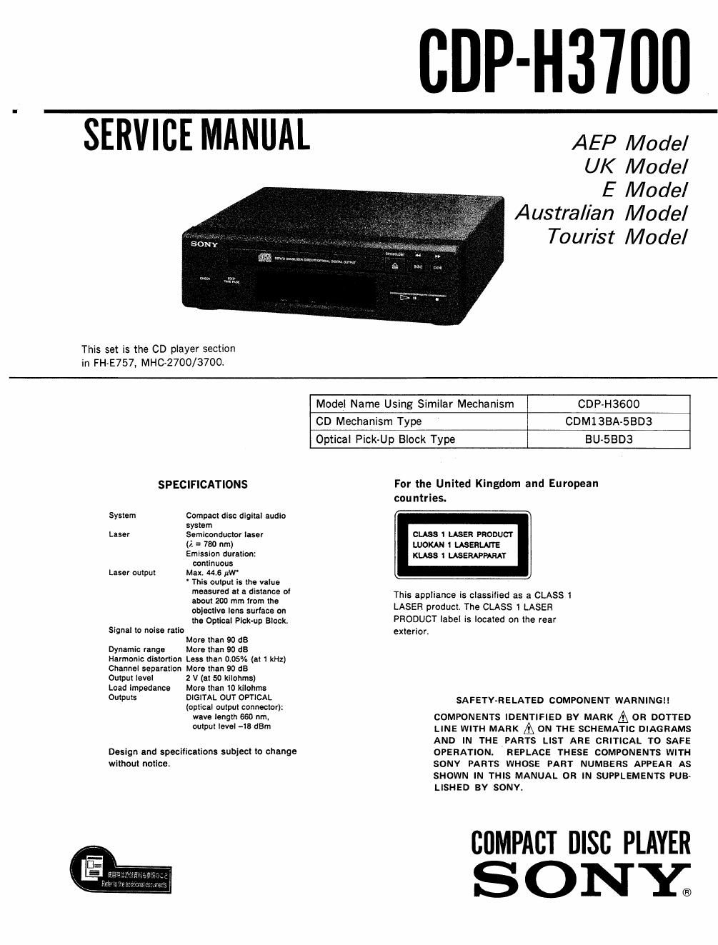
Sony cdp h 3700 service manual

This is the 35 pages manual for sony cdp h 3700 service manual.
Read or download the pdf for free. If you want to contribute, please mail your pdfs to info@audioservicemanuals.com.

Page: 1 / 35
left right
sony cdp h 3700 service manual

Extracted text from sony cdp h 3700 service manual (Ocr-read)


Page 1

CDP-H3'IIIII

AEP Model

UK Model

E Model
Australian Model
Tourist Model

SERVICE MANUAL

This set is the CD player section
in FH~E757. MHC»2700/3700l

Model Name Using Similar Mechanism CDP-H3600
CD Mechanism Type CDM13BA-SBDS
Optical Pick-Up Block Type BU-SBDB
SPECIFICATIONS For the United Kingdom and European
countries.
System Compact disc digital audio
system
Laser Semiconductor laser cuss 1 LASER PRODUCY
i). = no nm) LUOKAN t ussnurrs
Emission duration: «use 1 LASERAPPAMT
continuous
Laser output Max. 44.6 pw

' This output is the value
measured at a distance of
about 200 mm from the
objective lens suriace on
the Optical Pick-up Block.

Signal to noise ratio

More than 90 65
Dynamic range More than 90 dB
Harmonic distortion Less than 0.05% (at 1 kHz)
Channel separation More than 90 dB

Output level 2 V (at 50 kliohms)
Load impedance More than to kitohms
Outputs DIGITAL OUT OPTICAL

(optical output connector):
wave length 660 nm.
output level -18 darn

Design and specifications subject to change
without notice

This appliance is classified as 3 CLASS 1
LASER product. The CLASS 1 LASER
PRODUCT label is located on the rear
exterior.

SAFETY-RELATED COMPONENT WARNING! I

COMPONENTS IDENTIFIED BY MARK A 0R DOTTED
LINE WITH MARK A ON THE SCHEMATIC DIAGRAMS
AND IN THE PARTS LIST ARE CRITICAL T0 SAFE
OPERATION. REPLACE THESE COMPONENTS WITH
SONY PARTS WHOSE PART NUMBERS APPEAR AS
SHOWN IN THIS MANUAL OR IN SUPPLEMENTS PUB-
LISHED BY SONY.

CflMPACT DISC PLAYER

SONY.

Page 2

CDP-H37OO

TABLE OF CONTENTS

Section Title ng2
1. GENERAL
1-1, Parts Identification ......................... 3

2. TEST MODES
2-1. Test Mode of Display Microcomputer (IC40l) . . . .4
2-2. Test Mode of CD System Controller (ICZOZ) ...... 4

3. ELECTRICAL BLOCK CHECKING ............... 5
4. DIAGRAMS
4-1. Pin Description ........................ . .7
4-2. Block Diagram ....................... . .9
4-3. Printed Wiring Boards .................... .12
4-4. Schematic Diagram ........................ .15
4-5. Semiconductor Lead Layouts .................. 22
5. EXPLODED VIEWS
5-1. Chassis ...................................... 23
5-2. CD Block (CDM13BA-5BD3) .................. 24
5-3. Optical Pick-Up Block (BU-SBDB) .............. 25
6. ELECTRICAL PARTS LIST ...................... 26

MODEL IDENTIFICATION
- BACK PA N EL-

(9

E

SYSTEM CONTROL 2

4-948-753-11 (AE): AEP, UK, AUS model
4~948«753-32 (E) : E, TR model

IAUS: Australian model
CTR : Tourist model

NOTES ON HANDLING THE OPTICAL PICK-UP
BLOCK OR BASE UNIT

The laser diode in the optical pick-up block may suffer
electrostatic breakdown because of the potential diference
generated by the charged electrostatic load, etc. on clothing
and the human body.

During repair, pay attention to electrostatic breakdown and
also use the procedure in the printed matter which is included
in the repair parts.

The flexible board is easily damaged and should be handled
with care.

NOTES ON LASER DIODE EMISSION CHECK

The laser beam on this model is concentrated so as to be
focused on the disc reflective surface by the objective lens in
the optical pick-up block. Therefore, when checking the laser
diode emission, observe from more than 30cm away from the
objective lens,

LASER DIODE AND FOCUS SERCH OPERATION CHECK

1. Make POWER switch on with no disc inserted and disc
table closed.

2, Confirm that the following operation is performed while
observing the objective lens.

OConfirm that laser beam is spread.
0 Up and down motion of the objective lens, (3 times)