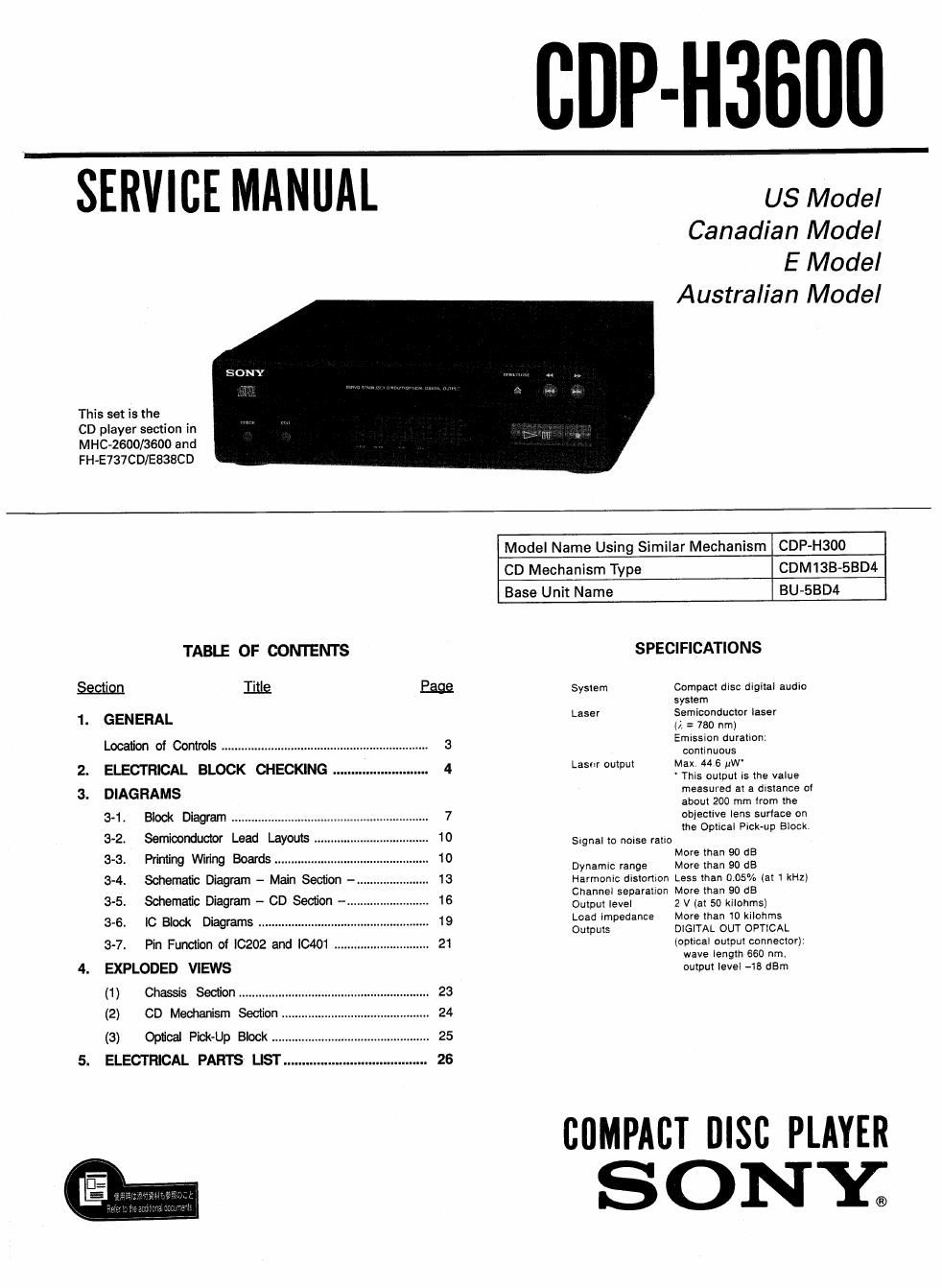
Sony cdp h 3600 service manual

This is the 47 pages manual for sony cdp h 3600 service manual.
Read or download the pdf for free. If you want to contribute, please mail your pdfs to info@audioservicemanuals.com.

Page: 1 / 47
left right
sony cdp h 3600 service manual

Extracted text from sony cdp h 3600 service manual (Ocr-read)


Page 1

cup-Ham

L s'ERVIc'E MANUAL-

US Model
Canadian Model
E Model
Australian Model

This set is the

CD player section in
MHC-2600/3600 and
FH-E737CD/E838CD

Model Name Using Similar Mechanism CDP

CD Mechanism Type CDM13B-SBD4
Base Unit Name BU~58D4
TABLE OF CONTENTS SPECIFICATIONS
3mm IIILQ Eggs System Compact disc digital audlo
t
1. GENERAL Laser :fmelgnductor laser
(/1 = 790 nm)
Location of Controls ................................. 3 5mm" mm
continuous
Laser output Max. 44 6 nW

ELECTRICAL BLOCK CHECKING
DIAGRAMS

3-2. Semiconductor Lead Layouts .
3-3. Printirg Wiring Boards .........
3-4. Schamafic Diagram - Main Section
3-5. Schematic Diagram - CD Seclion -

3-6. It: Block Diagrams .......................... ..

3-7 Pin Function of IC202 and l0401 21
4. EXPLODED VIEWS

(2) CD Meoharism Section 24

(3) Optical Pick-Up Block ......
5. ELECTRICAL PARTS LlST..

' This output is the value
measured at a distance of
about 200 mm Item the
objective lens surface on
the Optical Pick-up Blockv

Signal to noise ratio

More than 90 68
Dynamic range More than 90 dB
Harmonic distortion Less than 0.05% (at 1 kHz)
Channel separation More than 90 68

Output level 2 V (at 50 kilohms)
Load impedance More than 10 kilohms
Outputs DIGITAL OUT OPTICAL

(optical output conneclor):
wave length 660 nm.
output level -13 dBm

COMPACT msc PLAYER
SONY;

Page 2

CDP-H3600

LASER DIODE AND FOCUS SERCH OPERATION
CHECK

1. Make POWER switch on with no disc inserted and disc table
closed.

2. Confirm that the following operation is performed while observ-
ing the objective lens.

0 Confirm that laser beam is spread
9 Up and down motion of the objective lens. (3 times)

HOW TO OPEN THE DISC TRAY WHEN POWER
SWITCH TURNS OFF

BOTTOM VIEW

NOTES ON HANDLING THE OPTICAL PICK-UP
BLOCK OR BASE UNIT

FRCWT ON(CLOSE) OFFIOPEN)

l (:6 \ (DISC TRAY OPEN)
REAR

\
0
(I) Insen to 0 for tapering driver, etc, and turn in the direction of
arrow OFF. (Disc tray open)
Tray as come out little of front panel, pull out in the direction of
arrow 9 by hand.

(2)

The laser diode in the optical pick-up block may suffer electrostatic
break-down because of the potential difference generated by the
charged electmstatlc load, etc. on clothing and the human body.
During repair, pay attention to electrostatic break-down and also use
the procedure in the printed matter which is included in the repair
parts.

The flexible board is easily damaged and should be handled with
care.

NOTES ON LASER DIODE EMISSION CHECK

The laser beam on this model is concentrated so as to be focused on
the disc reflective surefaoe by the objective lens in the optical pick-
up block. Therefore, when checking the laser diode emission, ob
serve from more than 30 cm away from the objective lens.

SAFETY-RELATED COMPONENT WARNINGII

COMPONENTS IDENTIFIED BY MARK A 0R DOTTED LINE
WITH MARK A ON THE SCHEMATIC DIAGRAMS AND IN
THE PARTS LIST ARE CRITICAL TO SAFE OPERATION.
REPLACE THESE COMPONENTS WITH SONY PARTS WHOSE
PART NUMBERS APPEAR AS SHOWN IN THIS MANUAL OR
IN SUPPLEMENTS PUBLISHED BY SONY.

ATTENTION AU COMPOSANT AYANT RAPPORT
A LA sEcumTEI

LES COMPOSANTS IDENTIFIEs PAR UNE MAROUE A sun
LES DIAGRAMMES SCHEMATIOUES ET LA LISTE DES
PIECES SONT CHITIOUES POUR LA SECURITE DE FONC-
TIONNEMENT. NE REMPLACER cEs COMPOSANTS OUE PAR
DES PIECES SONY DONT LES NUMEROS SONT DONNEs
DANS CE MANUEL 0U DANS LEs SUPPLEMENTS PUBLIE's
PAR SONYI