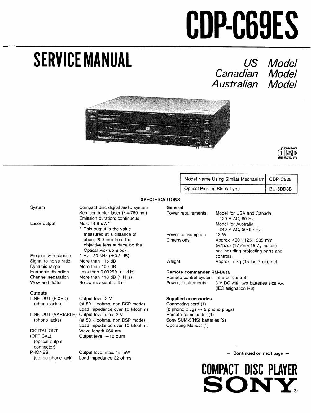
Sony cdp c 69 es service manual

This is the 24 pages manual for sony cdp c 69 es service manual.
Read or download the pdf for free. If you want to contribute, please mail your pdfs to info@audioservicemanuals.com.

Page: 1 / 24
left right
sony cdp c 69 es service manual

Extracted text from sony cdp c 69 es service manual (Ocr-read)


Page 2

CD P-C69ES

Optional accessory
Audio Optical connecting cord POO-15

Design and specifications subject to change without
notice.

Note on the Transit Key

The transit key on the bottom exterior of the unit protects
the optical system againstvshock during transportation.
Before operating the CD player, be sure to remove the key
by following the instructions on the label, and store it in a
safe place.

When transporting the unit, replace the key in its original
hole and lock it in place.

For the customers in Canada

- CAUTION: -
TO PREVENT ELECTRIC SHOCK, DO NOT USE THIS
POLARIZED AC PLUG WITH AN EXTENSION CORD.
RECEPTACLE OR OTHER OUTLET UNLESS THE
BLADES CAN BE FULLY INSERTED TO PREVENT
BLADE EXPOSURE

THIS APPARATUS COMPLIES WITH THE CLASS B
LIMITS FOR RADIO NOISE EMISSIONS SET OUT IN
RADIO INTERFERENCE REGULATIONS.

For the customers inrAustralia

This Compact Disc player
is classified as a CLASS 1
LASER product.

The CLASS 1 LASER
PRODUCT label is located
on the rear exterior.

CLASS '1 LASER PRODUCT
LUOKAN1 LASERLAITE

KLASS 1 LASERAPPARAT

SAFETY-RELATED COMPONENT WARNING

COMPONENTS IDENTIFIED BY MARK A OR DOTTED
LINE WITH MARK A ON THE SCHEMATIC DIAGRAMS
AND IN THE PARTS LIST ARE CRITICAL TO SAFE
OPERATION. REPLACE THESE COMPONENTS WITH
SONY PARTS WHOSE PART NUMBERS APPEAR AS
SHOWN IN THIS MANUAL OR IN SUPPLEMENTS PUB-
LISHED BY SONY.

TABLE OF CONTENTS
Section M Page
1. GENERAL
1-1. Location of Controls ....................................................... 5
2. DISASSEMBLY
2le Removal of Front Panel and Case Assemblies
2-2. Removal of Disc Tray Assembly - 6
273. Removal of Optical Pick-up Block Assembly
3. ELECTRICAL BLOCK CHECKING ~~~~~~~~~~~~~~~~~~~~~~~~~~~ 7
4. DIAGRAMS
4_1_ CIICUIT Boards Location ................................................... 9
4-2. Semiconductor Lead Layouts-'-
4-3. IC Block Diagrams
4-4. Block Diagrams ------
4.5. Printed Wiring Boards .................................................... 16
4-6. Schematic Diagram ....................................................... 21
5. EXPLODED VIEWS
5,]. Front panel and Case Assemblies ....................................... 25
5_2. Disc Tray Assembly ...................................................... 26
5.3 Chassis Assembly ................................................. 27
5-4. Optical Pick-up Block Assembly (BU-SBDSB) ~~~~~~~~~~~~ 28
6. ELECTRICAL PARTS LIST ..................................... 29

ATTENTION AU COMPQSANT AYANT RAPPORT
A LA sscunmsl

LES composmrs IDENTIFIES PAR UNE MAROUE A
sun LES DIAGRAMMES SCHEMATIOUES ET LA LISTE
DES PIECES sonr CRITIQUES POUR LA sécumré
DE FONCTIONNEMENT. NE HEMPLACER ces com.
POSANTS oue PAR DES PIECES SONY DONT LES
NUMéRos sonr ooNNés' DANS cs MANUEL ou
DANS LES SUPPLEMENTS PUBLIES PAR sonv.