Sony cdp c 26 service manual

This is the 30 pages manual for sony cdp c 26 service manual.
Read or download the pdf for free. If you want to contribute, please mail your pdfs to info@audioservicemanuals.com.

Page: 1 / 30
left right
sony cdp c 26 service manual

Extracted text from sony cdp c 26 service manual (Ocr-read)


Page 1

SERVICE MANUAL

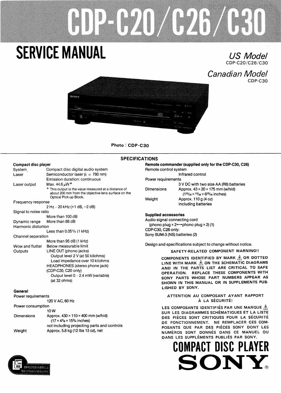
Photo 2 CDP-CBO

US Model

CDP-C20/C26/C30

Canadian Model

CDP-C3O

SPECIFICATIONS

Compact disc player

SystemA Compact disc digital audio system
Laser Semiconductor laser (A = 780 nm)

Emission duration: continuous
Laser output Max. 446 HW *

* This output is the value measured at a distance of
about 200 mm from the oblectlve lens su riace on the

Optical Pick-up Block.

Frequency response

2 Hz - 20 kHz (+1 dB, -2 dB)
Signal to noise ratio

More than 100 dB
Dynamic range More than 88 dB
Harmonic dlstortion

Less than 0.05% (1 kHz)
Channel separation

More than 95 dB (1 kHz)
Wow and flutter Below measurable limit

Outputs LINE OUT (phono jacks)
Output level 2 V (at 50 kilohms)
Load impedance over 10 kilohms
HEADPHONES (stereo phone jack)
(GDP-030, C20 only)
Output level 0 - 2.4 mW (variable)
(at 32 ohms)
General
Power requirements
120 V AC, 60 Hz
Power consumption
10 W
Dimensions Approx. 430 x 110 x 400 mm (wlhld)
(17 x 43/: x 153/4 inches)
not including projecting pans and controls
Weight Approx. 5.8 kg (12 lbs 13 oz), net

Remote commander (supplied only lor the GDP-030, 026)
Remote control system

Infrared control

Power requirements

3 V DC with two slze AA (R6) batteries

Dimensions Approx. 43 x 20 x 175 mm (wlhld)
(1 /16 X uIts X Gs/16 Inches)
Weight Approx 110 g (4 oz)
including batteries
Supplied accessories

Audio signal connecting cord

(phono plug x 2<->phono plug x 2) (t)
GDP-030, C26 only:
Sony SUM-3 (NS) batteries (2)

Design and specifications subject to change without notice

SA FETY-RE LATED COMPONENT WARNING! I

COMPONENTS IDENTIFIED BY MARK A 0R DOTTED
LINE WITH MARK A ON THE SCHEMATIC DIAGRAMS
AND IN THE PARTS LIST ARE CRITICAL TO SAFE
OPERATION. REPLACE THESE COMPONENTS WITH
SONY PARTS WHOSE PART NUMBERS APPEAR AS
SHOWN IN THIS MANUAL OR IN SUPPLEMENTS PUB-
LISHED BY SONY.

ATTENTION Au COMPQSANT AYANT RAPPORT
A LA secunirei

Les COMPOSANTS lDENTlFIES PAR UNE MAROUE A
son LES DIAGRAMMES SCHEMATIQUES e1- LA LISTE
DES PIECES sour cmnoues POUR LA sécualré
DE FONCTIONNEMENT. NE REMPLACER ces com.
POSANTS cue PAR DES PIECES SONY DONT Les
NUMEROS som DONNes DANS ce MANUEL ou
DANS Les SUPPLEMENTS PUBLIES PAR SONY.

CflMPACT nlsc PLAYER
SONZ

Page 2

CDP-CZO/C26/C30

TABLE OF CONTENS

Section Title

SECTION 1 GENERAL

1-1. Location and Function of Controls .......

SECTION 2 DISASSEMBLY

21. Front Panel (A) ........................
2-2. Front Panel (B) ..........................

SECTION 3 ELECTRICAL ADJUSTMENTS

SECTION 4 DIAGRAMS

4-1. IC Block Diagrams ....................
4-2. Circuit Boards Location ..................

SAFETY CHECK-OUT

After correcting the original service problem,
perform the following safety check before releasing
the set to the customer:

Check the antenna terminals, metal trim, metallized
knobs, screws, and all other exposed metal parts for
AC leakage. Check leakage as described below.

LEAKAGE TEST

The AC leakage from any exposed metal part to
earth ground and from all exposed metal parts to any
exposed metal part having a return to chassis, must
not exceed 0.5 mA (500 microampers). Leakage
current can be measured by any one of three
methods.

1. A commercial leakage tester, such as the
Simpson 229 or RCA WT-540A, Follow the
manufacturers instructions to use these instru
ments.

2. A battery-operated AC milliammeter. The Data
Precision 245 digital multimeter is suitable for
this job.

Section Title Page
4-3. Semiconductor Lead Layouts .............. 9
4-4, Printed Wiring Boards .................... 10
45, Schematic Diagram ...................... 13

SECTION 5 EXPLODED VIEWS

5-1, Cabinet Section .......................... 17
5-2. Disc Table Section ...................... 18
5-3. Frame Section .......................... 19
5.4. Optical Pick-Up Block (BU-5C) ............ 20
SECTION 6 ELECTRICAL PARTS LIST ........ 21

3, Measuring the voltage drop across a resistor by
means of a VOM or battery-operated AC volt-
meter. The limit indication is 0.7SV, so
analog meters must have an accurate low«
voltage scale. The Simpson 250 and Sanwa
SH-63Trd are examples of a passive VOM that
is suitable. Nearly all battery operated digital
multimeters that have a 2V AC range are
suitable. (See Fig. A)

To Exposed Metal
Parts on Set

0.15M: r 1.5km
L_ {

7- Earth Ground

A C
voltmeter
I0. 75 VI

L

F lg. A. Using an AC voltmeter to check AC /eakage.

.- N..- - ......... s ....... . ......... . ........... ..

SERVICING NOTE

NOTES ON HANDLING THE OPTICAL PICK-
UP BLOCK OR BASE UNIT

The laser diode in the optical pick~up block may
suffer electrostatic breakdown because of the poten-
tial difference generated by the charged electrostatic
load, etc. on clothing and the human body.

During repair, pay attention to electrostatic break-
down and also use the procedure in the printed
matter which is included in the repair parts.

The flexible board is easily damaged and should be
handled with care.

CAUTION

Use of controls or adjustments or performance
of procedures other than those specified herein
may result in hazardous radiation exposure.

NOTES ON LASER DIODE EMISSION CHECK

The laser beam on this model is concentrated so as to be
focused on the disc reflective surface by the objective
'lens in the optical pick-up block. Therefore, when check-
ing the laser diode emission, observe from more than 30
cm away from the objective lens.

__2_