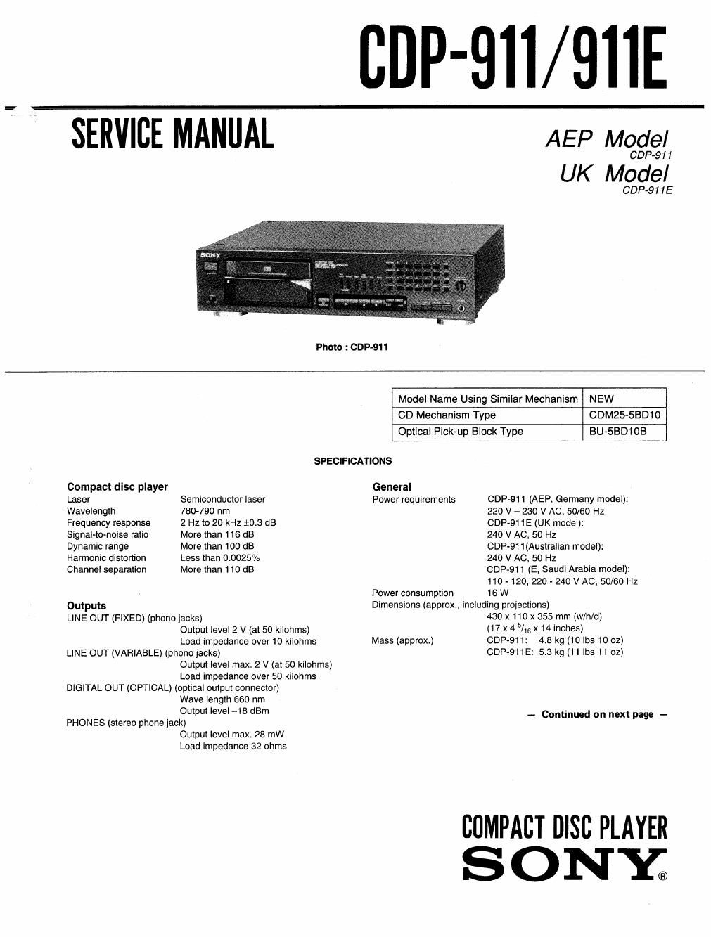
Sony cdp 911 service manual

This is the 32 pages manual for sony cdp 911 service manual.
Read or download the pdf for free. If you want to contribute, please mail your pdfs to info@audioservicemanuals.com.

Page: 1 / 32
left right
sony cdp 911 service manual

Extracted text from sony cdp 911 service manual (Ocr-read)


Page 2

Remote commander

Remote control system Infrared control

Power requirements 3 V DC with two R6 (size AA) batteries
Dimensions (approx., including projections)

62 x 18 x 175 mm (w/h/d)

(2 lz x 23/32X 7 inches)

Mass (approx.) 1309 (4.6 oz)
Supplied accessories
Audio cord (1) (2 phono plugs - 2 phono plugs)
Remote commander (1)

Sony SUM-3 (NS) batteries (2)

Design and specifications are subject to change without notice.

The laser component in this product is capable of emitting
radiation exceeding the limit lor Class 1.

This appliance is classified as a
CLASS 1 LASER product. The
CLASS 1 LASER PRODUCT
MARKING is located on the rear
exterior.

CLASS 1 LASER PRODUCT
LUOKAN 1 LASERLAITE

KLASS1 LASERAPPARAT

The lollowing caution label is located inside of the unit.

CAUTION : INVISIBLE LASER RADIATION WHEN OPEN.

AVOID EXPOSURE ro BEAM
. usvmo ussnsrnmno on Aanma ma

ADVAHSEL ' SIKKEBNEDSAFBRVDERE EH uoE AF summon
UNDGAUDS IETTELSE Fan s'raAMNe,

VAROI ; AVATTAESSA u suwawxrrus OHIfETTAESSA
mar ALTI'IINA USERSATEILVLLE

VAFINING : usansmmm; MAR DENNA DEL AR CPPNAD
OCH swans" AR unxoPPuo,

ADVARSEL : Usvmc usEnsmALmG MAR DEKSEL APNES
mm sxsmsnm FOR smug"

TABLE OF CONTENTS

$391M Lin 9. Bags
SECTION 1. SERVICING NOTE

SECTION 2. GENERAL
2-1. Parts Identification
2-2. Hooking Up the System

SECTION 3. DISASSEMBLY ........................................... 6
SECTION 4. ELECTRICAL CHECKING ........................... 7

SECTION 5. DIAG RAMS
5-1. IC Pin Functions .........
5-2. Semiconductor Lead Layouts .
5-3. Waveforms ..................
5-4. Block Diagram
5-5. Circuit Boards Location
5-6. Printed Wiring Board
5-7. Schematic Diagram.
5-8. IC Block Diagrams .
5-9, Terminal Connection of

Fluorescent Indicator Tube (FLD401)


SECTION 6. EXPLODED VIEWS
6-1. Cabinet Section
62. Front Panel Section .
6.3. CD Mechanism Section (CDM25-SBD10)
6-4. Optical Pick-up Block Section (BU-SBDIOB

SECTION 7. ELECTRICAL PARTS LIST 36

SAFETY-RELATED COMPONENT WARNINGII

COMPONENTS IDENTIFIED BY MARK .A OR DOTTED LINE
WITH MARK A ON THE SCHEMATIC DIAGRAMS AND IN
THE PARTS LIST ARE CRITICAL T0 SAFE OPERATION. REPLACE
THESE COMPONENTS WITH SONY PARTS WHOSE PART
NUMBERS APPEAR AS SHOWN IN THIS MANUAL OR IN
SUPPLEMENTS PUBLISHED BY SONY.

k2-