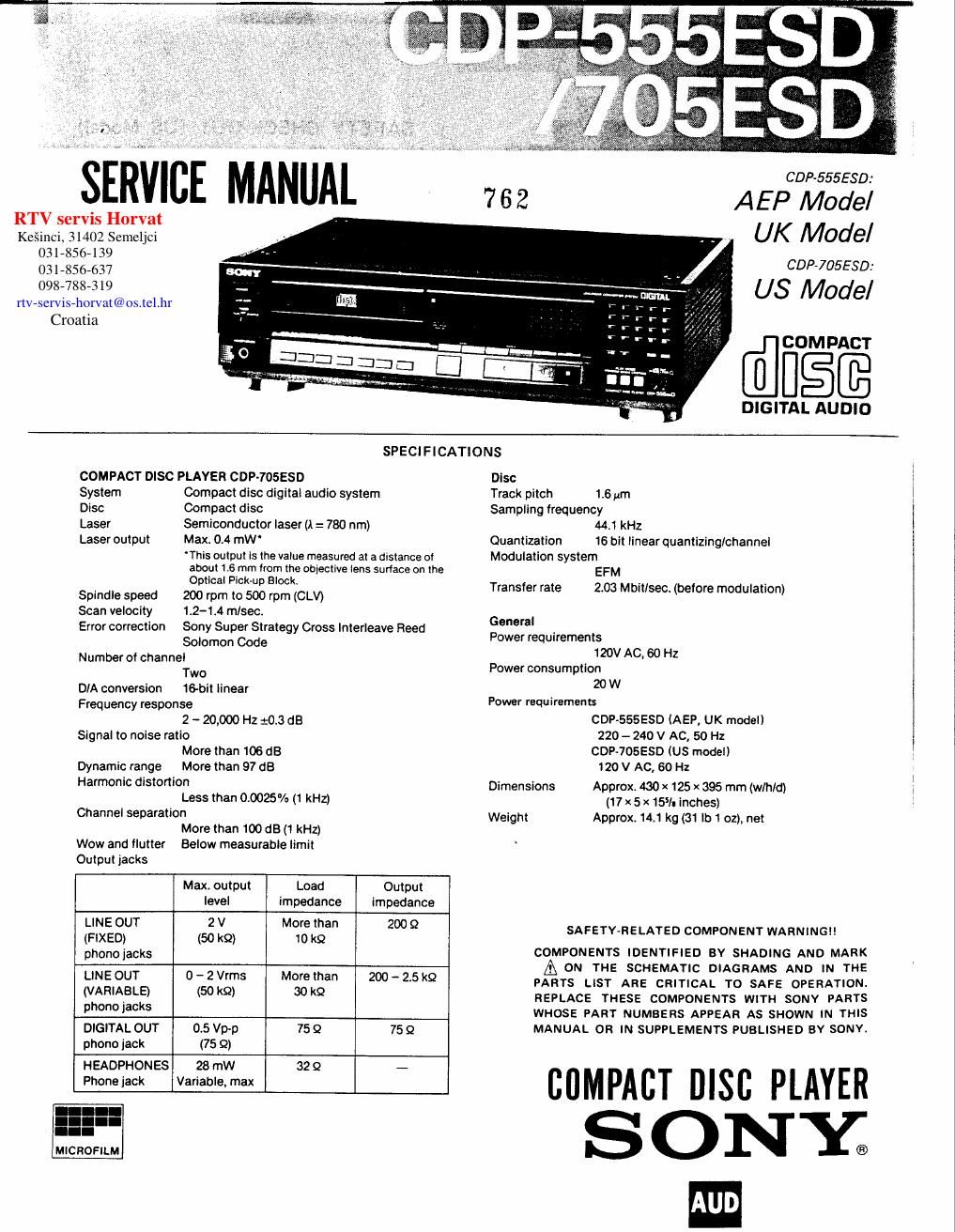
Sony cdp 705 esd service manual

This is the 32 pages manual for sony cdp 705 esd service manual.
Read or download the pdf for free. If you want to contribute, please mail your pdfs to info@audioservicemanuals.com.

Page: 1 / 32
left right
sony cdp 705 esd service manual

Extracted text from sony cdp 705 esd service manual (Ocr-read)


Page 1

Ke§inci, 31402 Semeljci

rtv-servis-horvat@us.tel.hr

SERVICE MANUA

RTV servis Horvat V -
031356-139
031-856-637
098-788-319

Croatia

GDP-555550:

7 6 2 A E P Model
UK Model

GDP-705580:

US Model

@3me

DIGITAL AUDIO

SPECIFICATIONS

COMPACT DISC PLAYER CDP-TOSESD

System Compact disc digital audio system
Disc Compact disc

Laser Semiconductor laser (A = 780 nm)
Laser output Max 0.4 mW'

This output Is the value measured at a distance oi
about 15 mm Irom the objective lens surlace on the
Optical Pick-up Block.

Spindle speed 200 rpm to 500 rpm (CLV)
Scan velocity 1.2-1.4 m/sac.
Error correction Sony Super Strategy Cross interleave Reed

Solomon Code
Number of channel

Two
DIA conversion 16-bit linear
Frequency response

2 - 20,000 Hz 20.3 dB
Signal to noise ratio

More than 106 (18
Dynamic range More than 97 dB
Harmonic distortion

Less than 0.0025% (1 kHz)
Channel separation

More than 100 dB(1kHz)
wow and flutter Below measurable limit
Output jacks

Max. output Load Output
level impedance impedance

LINE OUT 2 V More than 200 Q
(FIXED) (50 k9) 10 k9
phono jacks
LINE OUT 0 - 2 Vrms More than 200 - 2.5 k9
(VARIABLE) (50 k9) 30 k9
phone jacks
DIGITAL OUT 0.5 Vp-p 75 Q 75 9
phone jack (75 Q)
HEADPHONES 28 mW 32 $2 -
Phone jack Variable, max

MICROFILM

Disc
Track pitch 1,6 urn
Sampling frequency

44.1 kHz
Quantlzation 16 bit linear quantizing/channel
Modulation system
EFM
Transfer rate 2.03 Mbitlsect (before modulation)
General
Power requirements
120V AC. 60 Hz
Power consumption
20 W
Power requirements
CDPvSSSESD (AEP, UK model)
220 - 240 V AC, 50 Hz
CDP-705ESD (US model)
120 V AC, 60 Hz

Dimensions Approx. 430 x 125 x 395 mm (w/hld)
(17 x 5 x 15]. inches)
Weight Approx 14.1 kg (31 lb 1 oz). net

SAFETY-RELATED COMPONENT WARNING

COMPONENTS IDENTIFIED BY SHADING AND MARK

A ON THE SCHEMATIC DIAGRAMS AND IN THE
PARTS LIST ARE CRITICAL T0 SAFE OPERATION.
REPLACE THESE COMPONENTS WITH SONV PARTS
WHOSE PART NUMBERS APPEAR AS SHOWN IN THIS
MANUAL OR IN SUPPLEMENTS PUBLISHED BY SONY.

COMPACT Disc PLAYER
SONY?

Page 2

m
CDP-SSSESD/705ESD
CONTENTS
Title Page
SPECIFICATIONS .............................. 1
MODEL IDENTIFICATION 2
SAFETY CHECK (US model) ..................... 3
NOTES ON HANDLING THE OPTICAL BLOCK 4
FUNCTION OF CONTROLS ................. 5-6

TRABULE CHECK .
ELECTRICAL ADJUSTMENTS . . . . .8-10

IC BLOCK DIAGRAM ....... 11-12
CIRCUIT BOARD LOCATION. ..... 13
SCHEMATIC NOTE ............. .1A
SEMICONDUCTOR LEAD LAYOUTS . . .. ..... 14
MOUNTING DIAGRAM (Frexible Board) . 15-16
MOUNTING DIAGRAM (Main) ......... 17-20
SCHEMATIC DIAGRAM ............ 21-25
EXPLODED VIEWS AND PARTS LIST . 27-33
ELECTRICAL PARTS LIST .................. 34-33

----.--.-.ouo--.-.---.-----.-----a---.--ooo

MODEL IDENTIFICATION
-Specificatian Label «

CDP-SSSESD (AEP, UK, E model)
CDP-705ESD (US model)

SONY.

COMPACT DISC PLAYER

WW

MODEL NO. COP-555E8D

SERIAL NO,
MADE IN JAPAN

CDP-S55ESD

AEP, UK, E model: AC 220 -240 V ~ 50/60 Hz 20W

CDP-705ESD
US model: AC 120V ~ 60 HZ 20W

-.-----.-.-«-.- .-.---.-.-oo.---.-----¢-¢-a-----.-w

.--o.-------.o.-.---.-.-.-----.-.-.-.-.on-.o.-.---.-m

SAFETY CHECK-OUT (US Model)

After correcting the original service problem,
perform the following safety check before releasing
the set to the customer:

Check the antenna terminals, metal trim, metallized
knobs, screws, and all other exposed metal parts for
AC leakage. Check leakage as described below.

LEAKAGE TEST

The AC leakage from any exposed metal part to
earth ground and from all exposed metal parts to any
exposed metal part having a return to chassis, must
not exceed 0.5 mA (500 microampers). Leakage
current can be measured by any one of three
methods.

I. A commercial leakage tester, such as the
Simpson 229 or RCA WT-S40A. Follow the
manufacturers instructions to use these instru-
ments.

2. A battery-operated AC milliammeter. The Data
Precision 245 digital multimeter is suitable for
this job.

3. Measuring the voltage drop across a resistor by
means of a VOM or battery-operated AC volt-
meter. The limit indication is 0.75 V, so
analog meters must have an accurate low-
voltage scale. The Simpson 250 and Sanwa
SH<63Trd are examples of a passive VOM that
is suitable. Nearly all battery operated digital
multimeters that have a 2 V AC range are
suitable. (See Fig. A)

To Exposed Metal
Parts on Set

r.
Ac
0.15; gum / voltmeter
(0.75:0

;_J

-: Earth Ground

F ig. Al Using an AC voltmeter to check AC leakage.