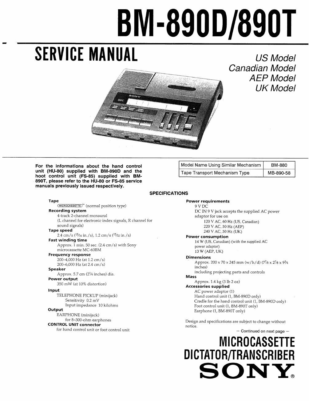
Sony bm 890 d service manual

This is the 40 pages manual for sony bm 890 d service manual.
Read or download the pdf for free. If you want to contribute, please mail your pdfs to info@audioservicemanuals.com.

Page: 1 / 40
left right
sony bm 890 d service manual

Extracted text from sony bm 890 d service manual (Ocr-read)


Page 2

Differences in supplied accessories

Model
Accessory BM-890D BM-BSOI
Hand Control Unit Supplied Not supplied
Cradle of Hand Supplied Not supplied
Control Unit

Foot Control Unit

Not supplied Supplied

Earphone Not supplied Supplied
TABLE OF CONTENTS
Section T_itl_e Page
Specifications .................................. 1
I. SERVICING NOTES ~~~~~~~~~~~~~~~~~~ 2
2. GENERAL
Features ................................ 7
Location and Function of Controls ~~~~~~~~~~ 8
Introduction -------------------------- 9
Setting Up ............................... 10
Operations .............................. 1 1
Additional Information -------------------- 19
3, DISASSEMBLY ......................... 20
4. MECHANICAL ADJUSTMENTS ~~~~~~~~~ 21
5. ELECTRICAL ADJUSTMENTS ~~~~~~~~~~ 22
6. DIAGRAMS
6-1, Printed Wiring Boards '
6-2. Schematic Diagram
6-3. IC Pin Functions ~~~~~~~~~
7. EXPLODED VIEWS ------------------- 38
8. ELECTRICAL PARTS LIST ~~~~~~~~~~~ 41

SA FETY-RELATED COMPONENT WARNING! |

COMPONENTS IDENTIFIED BV MARK A OR DOTTED
LINE WITH MARK A ON THE SCHEMATIC DIAGRAMS
AND IN THE PARTS LIST ARE CRITICAL TO SAFE
OPERATION. REPLACE THESE COMPONENTS WITH
SONY PARTS WHOSE PART NUMBERS APPEAR AS
SHOWN IN THIS MANUAL OR IN SUPPLEMENTS PUB-
LISHED BY SONV.

SECTION 1
SERVICING NOTES

[NOTES ON REPAIRING)

1,

STANDBY ON (5101) Switch
The STANDBY ON switch is not a switch for turning
ON/OFF the power source. Pay attention when repairing that
the electricity is turned on even if the STANDBY ON switch
is turned off.
0 The states when tumig off the STANDBY 0N switch are
as follows.
a. LCD (ND901) display will be turned off.
bl Motors (M901, 902) will be stopped,
c. Plungers (PM901) will be tumed offr
d, Any key input will be ignored.
The above items from a to d are controlled by the
microcomputer which makes the pin ® of [CNS (micro~
computer) become Low level.

[PINCH ROLLER cLEAING MODE] (If You Want to
Contlnue the Mechanical Operatlon wIth No Cassette)

1

With no cassette and with the cassette holder down (Cassette
lid: open), while holding down the cassette detection switch
(5601), press LISTEN D , FF DD and REW <4 buttons
on the this set to operate the mechanism

Even if the switch ($601) is released, in spite of no cassette,
the shut off function will not be in force, arrowing the
mechanism to continue to operate.

ATTENTION AUCOMPOISANT AVANT RAPPORT
A LA SECURITE!

LES COMPOSANTS IDENTIFIES PAR UNE MAROUE A
sun LES DIAGRAMMES SCHEMATIOUES ET LA LISTE
DES PIECES SONT CRITIQUES POUR LA sécumré
DE FONCTIONNEMENT. NE REMPLACER ces com-
POSANTS QUE PAR DES PIECES sowv DONT LES
NUMéRos SONT DONNES DANS ce MANUEL ou
DANS LES SUPPLEMENTS PUBLIES PAR SONY.