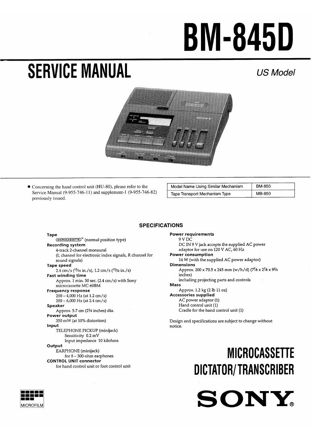
Sony bm 845 d service manual

This is the 28 pages manual for sony bm 845 d service manual.
Read or download the pdf for free. If you want to contribute, please mail your pdfs to info@audioservicemanuals.com.

Page: 1 / 28
left right
sony bm 845 d service manual

Extracted text from sony bm 845 d service manual (Ocr-read)


Page 1

BM-845_D

SERVICE MANUAL

US Model

.1
I
yum mum 4;.

MICROFILM

C Concerning the hand control unit (HU-80), please refer to the
Service Manual (9-955-746-1 I) and supplement-1 (9-955-746-82)
previously issued.

Model Name Using Similar Mechanism BM-850

M 3-850

Tape Transport Mechanism Type

SPECIFICATIONS

Tape
-" (normal posit-ion type)
Recording system
4-track 2-d1annel monaural
(L channel for electronic index signals, R channel for
sound signals)
Tape speed
2.4 cm/s (Ms in./s), 1.2 cm/s ('5/32 in./s)
Fast winding time
Approx 1 min. 50 sec. (2.4 cm/s) with Sony
microcassette MC-(SDBM
Frequency response
200 - 4,000 Hz (at 12 cm/s)
200 - 6,000 Hz (at 24 cm/s)
Speaker
Approx. 57 an (2% inches) dia.
Power output
350 mW (at 10% distortion)
Input
TELEPHONE PICKUP (minijack)
Sensitivity 0.2 mV
Input impedance 10 kilohms
Output
EARPHONE (minijack)
for 8 - 300-ohrn earphones
CONTROL UNIT connector
for hand control unit or foot control unit

Power requirements
9 V DC
DC [N 9 V jack accepts the supplied AC power
adaptor for use on 120 V AC, 60 Hz
Power consumption
14 W (with the supplied AC power adaptor)
Dimensions
Approx. 200 x 70.5 x 245 mm (w/h/d) (7/1! x 2% x 93/4
inches)
including projecting parts and controls
Mass
Approx. 1.2 kg (2 lb 1102)
Accessories supplied
AC power adaptor (1)
Hand control unit (1)
Cradle for the hand control unit (1)

Design and specifications are subject to change without
notice

MICHOCASSETTE
DICTATUR/TRANSCRIBER

SONY;

Page 2

SECTION 1
SERVICING NOTES

TABLE OF CONTENTS [NOTES FOR REPAIRING]
1. POWER (5101) Switch,
The Power switch is not a switch for turn off the power source.
Specifications ......................................................................... 1 Pay attention when repairing that the electricity is turned on even
if the POWER switch is turned STANDBY position,
1. SERVICING NOTES ........................................................... z o The states when tum STANDBY position of the POWER switch
are as follows.
2. GENERAL a, LCD (ND901) display will be turned off.
Location and Function of Controls . 3 b. Motors (M901, 902) will be stopped.
About This Manual 4 c. Plungers (PM901, 902) will be turned offr
Features ................. 4 d. Any key input will be ignored.
Operation Flow Chan .. 4 The above items from a" to d" are controlled by the microcom-
Power Connection . 5 puter which makes the pin @ of IC109 (microcomputer) become
Setting Up the Unit 5 Low Level.
Dictation ..... 6
Transcription .. 8
Erasing ....... 10
Example of Dictation and Transcription 10
Troubleshooting Guide 11
Alarm System 11
Maintenance ,,,,,, ll
3. MECHANICAL ADJUSTMENTS .................................... 12
4. ELECTRICAL ADJUSTMENTS ..................................... 13
5. EXPLANATIONS OF IC TERMINALS ........................... 15
6. CIRCUIT DESCRIPTION ................................................. 17
7. DIAGRAMS

7-1. Block Diagram ..........
7-2. Printed Wiring Boards .,
7-3. Schematic Diagram.

24
27

8. EXPLODED VIEWS
8-1, Cabinet Section ..
8-2. Mechanism Deck ection ( ) ..
8-3. Mechanism Deck Section (2) ..

9. ELECTRICAL PARTS LIST 34

SAFETY-RELATED COMPONENT WARNINGII

COMPONENTS IDENTIFIED BY MARK A OR DOTTED LINE WITH
MARK A ON THE SCHEMATIC DIAGRAMS AND IN THE PARTS
LIST ARE CRITICAL TO SAFE OPERATION.

REPLACE THESE COMPONENTS WITH SONY PARTS WHOSE
PART NUMBERS APPEAR AS SHOWN IN THIS MANUAL OR IN
SUPPLEMENTS PUBLISHED BY SONY.