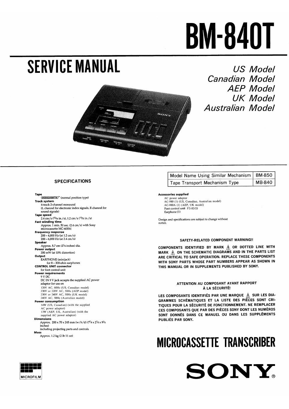
Sony bm 840 t service manual

This is the 22 pages manual for sony bm 840 t service manual.
Read or download the pdf for free. If you want to contribute, please mail your pdfs to info@audioservicemanuals.com.

Page: 1 / 22
left right
sony bm 840 t service manual

Extracted text from sony bm 840 t service manual (Ocr-read)


Page 1

BM-84UT

SERVICE MANUAL

US Model
Canadian Model
AEP Model

UK Model
Australian Model

53'"

MICROFILM

SPECIFICATIONS

Tape
W (normal position type)
Track synem
(rack 2-channel monaurdl
(L channel (or eleclronic index signals, R channel fox
sound signals)
Tape speed
2A ml: (/15 in./s), 1.2 (Tn/s (/32 LIL/SI
rm winding ("we
Approx. 1 min. 50 sec. (2.4 cm/s) with Sony
micracasselle MC-éOBM
Frequency response
200- 4 000 Hz (at I.2cTn/s)
200 ,000 Hz (at 2.4 tin/SI
Speaker
Applox. 5.7 cm (Z'A inches) dis.
rower omput
350 MW (at 10% distortion)
Output
EARIHONE (minijnck)
for s - mohm earphones
CONTROL UNIT connector
for Tool control unit
Power rcquiuments
9 V DC
DC IN 9 v jack accepIs The supplied AC power
adapwr {or use on
IZOV AC, 60H1(US. Canadian model)
230v or 220v Ac, son (AEP model)
230v or zwv Ac, 50H: (UK model)
240v AC, 50H: (AuszrdIlan model)
Pow" consumption
14W (Us, Canadian) (wnh the supplied
AC power adaplor)
ISW (AEP, UK. Australian) (wnli the
supplied AC power adanior)
Dimenslons
Apprax. 200 x 7D x 245 mm (w/n/d) (7% x 27/. x 9%
inches)
including pmkclIng pans and controls
Mass
Appmx. 1.2 kg (2 lb ll oz)

Model Name Using Similar Mechanism BM-850
Tape Transport Mechanism Type MB-840

Amssarm suppfled
AC power adaplor
A0980 (I) (us, Canadian, Ausualian modeI)
AC-980A (I) (AEP, UK model)
Fool comm! unil F3350)
Earphone (1)

Design and speulicalions are Subietl To change wilhoul
notice.

SAFETY-RELATED COMPONENT WARNINGII

COMPONENTS IDENTIFIED BY MARK A OR DOTTED LINE WITH
MARK [Q ON THE SCHEMATIC DIAGRAMS AND IN THE PARTS LIST
ARE CRITICAL T0 SAFE OPERATION. REPLACE THESE COMPONENTS
WITH SONY PARTS WHOSE PART NUMBERS APPEAR AS SHOWN IN
THIS MANUAL OR IN SUPPLEMENTS PUBLISHED BY SONY.

ATTENTION AU COMPOSANT AYANT RAPPORT
A LA sEcumTEl

LEs composmrs IDENTIFIES PAR UNE MARQUE A SUR LEs DIA-
GRAMMES SCHEMATIQUES ET LA LlsTE DES PIECES sour cm-
TIQUES POUR LA sEcuRlTE DE FONCTIONNEMENT. NE REMPLACER
CES COMPOSANTS QUE PAR DES PIECES SONY DONT LEs NUMERos
$0NT DONNES DANS cE MANUEL ou DANS LEs SUPPLEMENTS
PuaLlEs PAR sonv.

MICRIIBASSETTE TRANSCRIBER
S ONY.

Page 2

TABLE OF CONTENTS

Section E? Page
1. SERVICING NOTES

Notes for Repairing .............................. 2
2. GENERAL

Location and Function of Controls . ..... 3

Operation Flow Chart ........ . .4

Power Connection ..... . .4

Setting Up the Unit .............

Transcription .....................

Erasing ...........................

Alarm System ...................................... 7
3. CIRCUIT DESCRIPTION

Microcomputer #PD75308GF-K63-3B9 (IC109) ........ 8
4. MECHANICAL ADJUSTMENTS ......... 14
5. ELECTRICAL ADJUSTMENTS ................ 15
6. DIAGRAMS
6-1. Printed Wiring Boards .......................... 18
6'2. Schematic Diagram iiiiiiiiiiiiiiiiiiiiiiiiiiiiii 21
7. EXPLODED VIEWS
7-14 Cabinet Section ................................ 25
7-2. Mechanism Deck Section (1) . . .26
7-3. Mechanism Deck Section (2) H27
8. ELECTRICAL PARTS LIST ,,,,,,,,,,,,,,,,,,,,,, 28

SECTION 1
SERVICING NOTES

[NOTES FOR REPAIRING}

1.

POWER (3101) Switch
The POWER switch is not a switch for turn off the power
source. Pay attention when repairing that the electricity
is turned on even if the POWER switch is turned STAN-
DBY position.
O The states when turn STANDBY position of the
POWER switch are as follows.
a. LCD (ND901) display will be turned off.
b. Motors (M901, 902) will be stopped.
c, Plungers (PGQOI, 902) will be turned off.
cl. Any key input will be ignored.
The above items from a to cl are controlled by the
microcomputer which makes the pin (SE of IC109 (mi-
crocomputer) become Low level.