Sony an lp 1 service manual

This is the 14 pages manual for sony an lp 1 service manual.
Read or download the pdf for free. If you want to contribute, please mail your pdfs to info@audioservicemanuals.com.

Page: 1 / 14
left right
sony an lp 1 service manual

Extracted text from sony an lp 1 service manual (Ocr-read)


Page 1

AN-LP1

SERVIIIEIVIANIJAL WM

Canadian Model
AEP Model

UK Model

E Model
Australian Model
Tourist Model

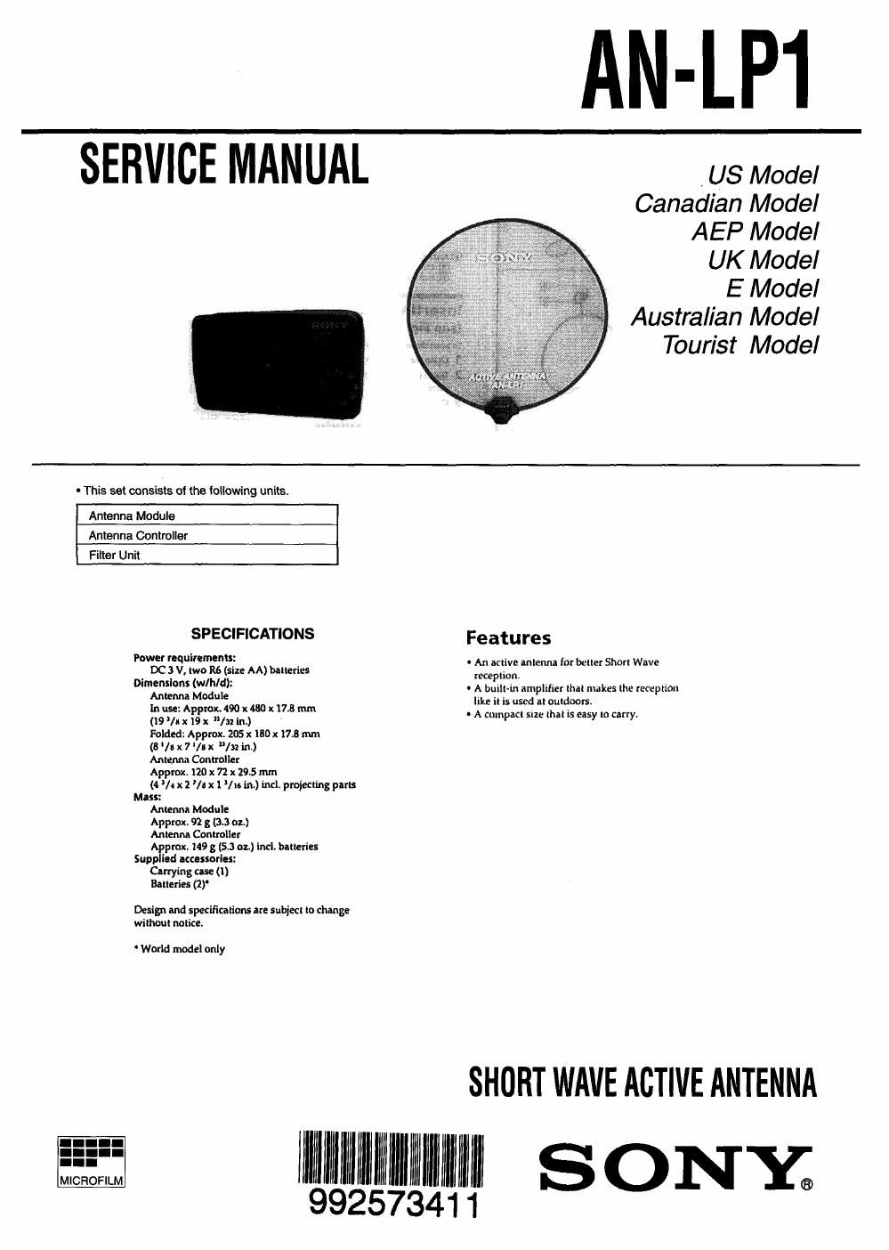
0 This set consists of the following units.

Antenna Module
Antenna Controller
Filter Unit

SPECIFICATIONS Features

Power nq uirements: , , ,

DC 3 V, two R6 (size All) binaries 2:22:13: antenna for butter Short Wave
Dimenslons (WINCH: - A built-in amplifier that nukes the reception

3an Module 430 17.8 like it is used at outdoors,

(1915;933:0322 hi) x mm ' A compact Elle that is easy In carry.

Folded: Approx. 205 1 I80): 17.8 mm

(B /I x 7 '/5x /3: in.)

Antenna Controller

Approx. 120 x 72 x 29.5 mm

(4 A x 2 'In x l lu in.) incl. projecting pm:
Mass:

Antenna Module

Approx 92 g (3.3 or.)

Antenna Controller

Approx. 149 g (5.3 all) incl. batteries
Supplied accessories:

Carrying use (1)

Batteries (1)

Design and specifications are subject to clung:
without notice.

World model only

SHORT WAVE ACTIVE ANTENNA

llllslallll 9llzllllllllllllllll llllll S ONY;

9257341

Page 2

This section is extracted from
Instruction manual.

SECTION 1
GENERAL

Location and Functi n
of Controls (see Fig. I)

(D Ante nna controller

Cord winder
Long card

a rowan IWltch
POWER lamp

l3] l-REQ stsLucr control
Ballery compartment
Short cord

® Antenna module

an;
it] Suction cup

Inserting the Batteries
(see Fig. IE)

Toinsert lhehallertex into the antenna controller
1 Opentheballerycompanmentlldt

2 insert two R6 (nu AA) batteries with
correct polarity

3 Close the lid

Battery lite on rlry batteries
Sony in (ma AA) dry hat-uric:
approx cu hours

when to replace the batteries
When the haltenes became weak. the town
lamp dim: Replace hmh battle-m with new
oneI wtten itlebauenea gel Exhausted. the
rowan lamp pas ottwtitt the operation

Notes on the batteries

mtmko

mantle! hm

- Dorm charge the dry batienea

- Do nut zany uta dry bunnies with wins in
other metaite obteetr lteiin mil heat it Iht
plant! and negative lemmlll ot the batteries
in acntieniaity contacted by a melallac obtacl

- when you an mt going to use the unit tor a
lung (lute. rarntm in. ballerlel in avoid
damage (tom battery leakage and corrosinn

Setting Up (see Fig. I)

Ilacelhtanlennallmdulebylhewtndnwm
where the reception is well Then Conner! the
antenna controller, amt-via module and Min

1 Unlold the anlenml module Ilowly.
when unioldtng the antenna modflhbe
careful not totui you-sell truth II or your
aurroundtnpmther people and non-durable
items)

2 Pull out the long «ml with a double put
plug [mm the antenna controller until it
stops and connect it In the antenna
module

3 Attach the antenna module to a glass
window or the curtain

4 Take out the short cord with a single
pm plug from the antenna tontmller
and connect it to external antenna lack
ol lite radio

Notes

- Donor use the unit outdoor:

. You may not get but racepttnn II the tang cord
at the nniaina mntrolter |I ltept rim the who
Keep the long «ant u in array inini the rat-tut
as possible.

I Keep the radio and antenna mnnoileuway
[mm the W. tekpme, pennant mrtpttter and
floureieeni hanpi to avoid m Inwdfllmtfl

__-
Operating the Active
Antenna (see Fig. IE)

1 Set the POWER switch on the antenna

controller to 0 Ni
rower: lamp will be tit

2 Adtutt the FREQ SELECT control
Band Frequency illmSELECl

Meier range :utitwl
tum

75ml: M50 4

6

Notes on the Radio

- For detallam ndlo operation. titer in ii:
tnainirnnna nuntutl

- Set the DXILOCAL awiidi ottlte radio It: ntt
when using the active antenna

Note

- ms Kllve mlcmu it only in sw (Shun
Wave) When you receive FM, MW ur LW be
sure u: tit-pin; thl ultve nnltnmi It yuu leave
the aenve antenna pluued In to the indie, the
telescopic nnlennn and the term: bitt- iiniennti
will not operate

To turn off the antenna controller
Sel the Powzn switch It) arr/sum)"

when using Icr-sw1ooot or
[CF-SW7EOBG with the active

a ntlnne

When the antenna contratler is connected to lite
EXT ANltnck a! tilt radio, the puwer supply at
the antenna mntroller ii bathed in the power
supply ol the radio Set the POWER awiutt oldie
antenna controller to OFF/STANDBY

When using lCF-SWlODS/SW1DOE
with the active antenna

The power supply at the antenna ronlmller is
linked to the power iuppty ol the radio, but liill
may nol work properly Set the POWER swlbdl of
theanimna mntrotler to ON

Using ICF-SWIO, lCF-SW11 with the
active antenna

We rin not rrrotruitend tiring lCtstrl mitt this
MW

Please mmuli your nearest Suty dealer

After use (see Fig. E)

1 Dtscoitnect the antenna module.
antenna controller and radio.

2 Reel up the lung cont

3 Wrap the short cord to the antenna
controller and set it tn place

4 th1i Ind told the antenna module and
then put it tn the carrying use

-----
Precautions

- Donotlelve the-intimate lontimmhrheat
router, or iii a place autmei to direct nail-gilt.
Intensive dull, or median-cl) mock

- Use the unit Wilhln a temperature range uto'c
tn ttrc (31'F to low).

- Do not use the unit when there ii high
humidity like the bathroom

- When you in: Mt going in use the unit lot a
long period of nine, nmwl the hniienea to
award diunage lrurn battery leakage and
corrosion

- Do not wash the anlenna module

- When uniting the antenna module, do not bend
it by tone or break it

. when you are not going to late the unit tar a
long period at time. put it away