Siel cruise schematics

This is the 3 pages manual for Siel cruise schematics.
Read or download the pdf for free. If you want to contribute, please mail your pdfs to info@audioservicemanuals.com.

Page: 1 / 3
left right
Siel cruise schematics

Extracted text from Siel cruise schematics (Ocr-read)


Page 1

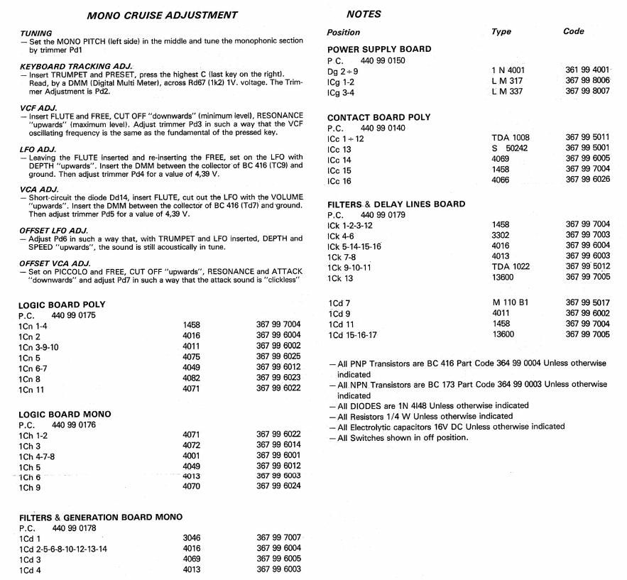
MON 0 CRUISE ADJUSTMENT

TUNING
7 Set the MONO PlTCH (left side) in the middle and tune the monophonic section
by trimmer Pdi

KEYED/IND TRACKING ADJ.

- Insert TRUMPET and PRESEI, press the highest C [last key on the right).
Read, bv a DMM [Digital Multi Meter), across Rd67 (1k2) 1V. voltage. The Trim-
mer Adjustment is m.

VCF ADJ.

7 insert FLUTE and FREE, CUT OFF downwards (minimum level), RESONANCE
"upwards" (maximum leveil. Adjust trimmer Pd3 in such a way that the VCF
oscillating frequency is the same as the fundamental of the pressed key.

LFO ADJ.

- Leaving the FLUTE inserted and rerinsening the FREE, set on the LFO with
DEPTH "upwards". lnsen the DMM between the collector at BC 416 (T091 and
ground. Then adjust trimmer Pd4 for a value of 4,39 V.

VCA ADJ,

_. Shon-circuit the diode Dd14, insert FLUTE, cut out the LFO with the VOLUME
upwards. Insert the DMM between the collector of EC 416 (T117) and ground.
Then adjust trimmer Fd5 for a value of 4,39 V.

OFFSET LFO ADJ.
~ Adjust Pdfi in such a way that, with TRUMPET and LFD inserted, DEPTH and
SPEED "upwards, the sound is still acoustically in tune.

OFFSET VCA ADJ.
- Set on PICCOLO and FREE, CUT OFF "upwards", RESONANCE and A'I'I'ACK
downwards" and adjust Fd7 in such a way that the attack sound is clickless"

LOGIC BOARD POLY
RC. 440 99 0175

1Cn 1-4 1458 367 99 7004
1Cn 2 4016 367 99 6004
icn 3-9-10 4011 367 99 6002
1Cn 5 4075 367 99 6025
1Cn 6-7 4049 367 99 6012
1Cn 8 4082 367 99 6023
1Cn 11 4071 367 99 6022
LOGIC BOARD MONO

P.C, 440 99 0176

1Ch 1-2 4071 367 99 6022
ICh 3 4072 367 99 6014
1Ch 4-7-8 4001 367 99 6001
ICh 5 4049 367 99 6012
iCh 5 4013 36] 99 6003
1Ch 9 4070 367 99 6024
FILTERS 8t GENERATION BOARD MONO

PL. 440 99 0178

1Cd 1 3046 367 99 7007
1Cd 2-5-6-8-10-12-13-14 4016 367 99 6004
1Cd 3 4069 367 99 6005
1Cd 4 4013 367 99 6003

NOTES

Position Type Code
POWER SUPPLY BOARD

PC. 440 99 0150

D9 2+9 1 N 4001 361 99 4001
[Cg 1-2 L M 317 367 99 8006
ICg 3-4 L M 337 367 99 8007
CONTACT BOARD POLV

P.C. 440 99 0140

ICc 1*12 TDA 1008 367 99 5011
ICC 13 S 50242 367 99 5001
ICC 14 4069 367 99 6005
Sc 15 1458 367 99 7004
1C!) 16 4066 367 99 6026
FILTERS & DELAV LINES BOARD

P.C. 440 99 0179

le 1-2-3-12 1458 367 99 7004
le 4-6 3302 367 99 7003
le 5-14-15-16 4016 367 99 6004
16k 7-8 4013 367 99 6003
le 9-10-11 TDA 1022 367 99 5012
1Ck 13 13600 367 99 7005
1Cd7 M110 B1 367995017
1Cd 9 4011 367 99 6002
1Cd 11 1458 367 99 7004
10115-1617 13600 367 99 7005

~All PNP Transistors are BC 416 Part Code 364 99 0004 Unless othenrvise
indicated

- All NPN Transistors are BC 173 Part Code 364 99 0003 Unless otherwise
indicated

-All DIODES are 1N 4l48 Unless otherwise indicated

-All Resistors 1/4 W Unless otherwise indicated

-All Electrolytic capacitors 16V DC Unless otherwise indicated

>AII Switches shown in off position.

Page 2

MONO SECTION