Shure uc4 wireless receiver service manual

This is the 33 pages manual for shure uc4 wireless receiver service manual.
Read or download the pdf for free. If you want to contribute, please mail your pdfs to info@audioservicemanuals.com.

Page: 1 / 33
left right
shure uc4 wireless receiver service manual

Extracted text from shure uc4 wireless receiver service manual (Ocr-read)


Page 1

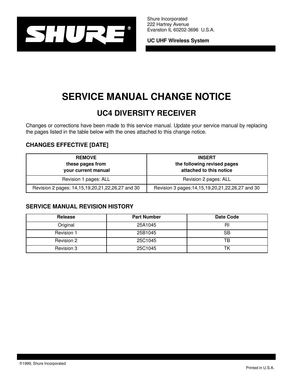
1999, Shure Incorporated Printed in U.S.A. 25C1045 (TK) Service Manual UC4 Diversity UHF Receiver 25C1045 (TK) Characteristics General The Shure UC4 Diversity UHF Receiver is a microprocessor- controlled single diversity receiver operating in the 692 to 716 MHz and 774 to 862 MHz frequency range. The UC4 is used in mid-level installed sound, rental, and concert sound applications. Controls and Connectors 1. Diversity Indicators 2. Squelch Control 3. Rf Level Indicators 4. Audio Level Indicators 5. Low Transmitter Battery Indicator 6. Group Rotary Switch 7. LED Display 8. Channel Rotary Switch 9. Equalization ( EQ ) Adjustment Controls10. Level (Volume) Control 11. Power On/Off Switch 12. Power Input Connector 13. Balanced ( LOW Z ) Output Connector 14. MIC/LINE Side Switch 15. Unbalanced ( HIGH Z ) Output Connector 16. LOGIC OUT Connector 17. Antenna Input Connectors Figure 1.UC4 Controls and Connectors A B R 1 5 8 10 3 4 6 12 11 9 13 14 15 16 17 7 2 Service Note: Shure recommends that all service procedures be performed by a Factory- Authorized Service Center or that the product be returned directly to Shure Incorporated. Licensing: Operation may require a user license. Frequency or power-output modifica- tions may violate this products approvals. Contact your countrys communications authori- ties.

Page 2

Shure UC4 Diversity Receiver 2 Parts Designations 25C1045 (TK) Circuit Description The audio circuit and rf circuit description will describe only one channel because the other channel is identical for both. The local oscillator (LO) section is common for both channels and will be described separately. Audio Section Figure 2.UC4 Audio Section Block Diagram AUDIO A AUDIO B 4-POLELPFILTERCOMPANDER DE-EMPHASISTONE CONTROLOUTPUT STAGE XLR OUT 1/4 OUT TO AUDIO LEVEL BAR DISPLAY SQUELCH NOISE A NOISE B MARCADDIVERSITY CIRCUITTONE KEY DETECTORMUTING CIRCUIT LOW BATTERY DETECTOR TTLCIRCUIT TTL OUT The audio for each channel comes from the appropriate channel detector output of the rf section. Each channels audio then enters its own adjustable gain stage. This adjustable gain stage is used to match the audio levels coming from each rf channel, as well as to set the correct level necessary for the compander. From the gain stages, each channel enters an analog switch. Noise outputs also come from each channel detector outputs. Each noise output enters a bandpass noise filter that measures the 50 kHz noise present in the audio signal. The noise level is proportional to the signal- to-noise ratio of the channel. In the MARCAD diversity system, a rectified version of the noise is sent to a bank of comparators. A version of the channel noise that is 6 dB less also enters the comparators. The noise from one channel is compared to the noise from the other to make sure they are within 6 dB of each other. If the noise levels are within 6 dB of each other, the comparators send a logic high signal to the control of each channels analog switch, allowing the audio to pass through.