Shure pe610 owners manual

This is the 6 pages manual for shure pe610 owners manual.
Read or download the pdf for free. If you want to contribute, please mail your pdfs to info@audioservicemanuals.com.

Page: 1 / 6
left right
shure pe610 owners manual

Extracted text from shure pe610 owners manual (Ocr-read)


Page 1

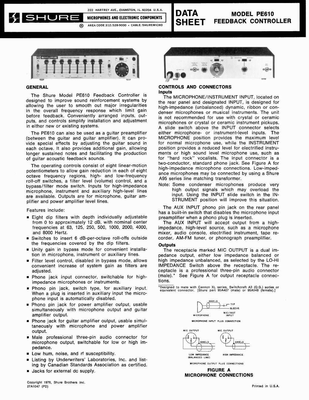
?, UJ 0 g t; -5 y-l02 4681 P 4681 2 4683 2 $ 20 I GO I000 10,000 20,000 L, ie FREOUENCY (HZ) FIGURE BI- EACH FILTER AT 6 dB ATTENUATION - m m 0 $ -5 2 -10 W 2 -15 g 2 4 681 2 4 681 2 4 681 2 2 20 100 1000 10,000 20poo z FREQUENCY (HZ) FIGURE 82- EACH FILTER AT MAXIMUM ATTENUATION FIGURE B INDIVIDUAL OCTAVE FILTER FREQUENCY CHARACTERISTIC (TYPICAL) The phono pin jack marked OUTPUT TO POWER AMPLIFIER is a high-impedance, high-level output de- signed primarily to feed a power amplifier or auxiliary input requiring 0.1 to 2 volts. The phono jack marked OUTPUT TO GUITAR AM- PLIFIER is designed to feed a guitar or similar instru- ment amplifier input requiring 15 to 300 millivolts. Accessory 30 Volts DC These rear panel jacks are used as a power input when using the Model A67B Battery Power Supply (Accessory). Controls Power Switch and Pilot Light: The power ON-OFF switch controls operation of the unit when it is powered either by the ac line or by an external dc source. The pilot light indicates operation only when ac power is used. FILTER FREQUENCY Controls: The eight linear-motion FILTER FREQUENCY con- trols located on the front panel are used for adjusting the level of eight octave-spaced bands having center frequencies of 63 Hz, 125 Hz, 250 Hz, 500 Hz, 1 kHz, 2 kHz, 4 kHz, and 8 kHz respectively. The levels of the octave-spaced bands are individually and continuously adjustable from flat at full up position to approximately 12 dB cut at full down position. Figures B1 and 82 illustrate the frequency response characteristic of each octave filter when adjusted for 6 dB cut and full cut. BELOW 63 and ABOVE 8K Switches: The BELOW 63 Slide Switch reduces the gain of frequencies below the 63 Hz octave band when placed in the down position, and the ABOVE 8K Slide Switch reduces the gain of frequencies above the 8 kHz octave band when placed in the down position. Figure C shows the frequency response characteristics of these filters. 8 W In g 0 B -5 Y-I02 4 6 81 2 4 6 51 2 4 6 81 2 E 20 100 1000 lop00 20.000 FREOUENCY (HZ) W a BELOW 63 AND ABOVE 8K FILTER FREQUENCY CHARACTERISTICS (TYPICAL) FIGURE C MODE (Filter-Bypass) Switch: In the BYPASS position, the MODE switch disables the filters and the FILTER LEVEL Control and sets gain from AUX INPUT to OUTPUT TO POWER AMPLI- FIER or MICROPHONE INPUT to MIC OUTPUT, at ap- proximately unity. The filters and FILTER LEVEL Controls are operative in the FILTER position. FILTER LEVEL Control: The FILTER LEVEL Control provides up to 24 dB gain when the MODE Switch is in the FILTER position, as well as gain reduction below unity. The FILTER LEVEL Control is used to increase system gain as filters are adjusted. A FILTER LEVEL setting of ap- proximately 4 provides unity gain with the MODE Switch in the FILTER position and all FILTER FRE- QUENCY Controls in the full up position. INSTALLATION: The PE610 is typically connected in the auxiliary, high-level line between the mixer/preamplifier and the power amplifier, or between the microphone and the mixer/preamplifier in single-microphone systems. Any combination of inputs and outputs available may be used, however, according to the particular needs of the user. To use the PE610 to equalize a single microphone in a Shure Vocal Master (VA300 or VA302) system, connect the microphone to the PE610 INPUT and the PE610 MIC OUTPUT to a Vocal Master Console MI- CROPHONE INPUT. Set the PE610 MIC OUTPUT IMPEDANCE Switch to HI (for VA300) or LO (for VA302). Additional PE6lOs may be added, one per channel, to provide an optimum feedback control system. To use a single PE610 to provide overall equaliza- tion of a Vocal Master Console, connect a length of low-capacitance, single-conductor, shielded cable with phone plugs attached to each end between the Con- sole ECHO/TO INPUT jack and the PE610 INPUT connector and set the INPUT switch to INSTRUMENT. Connect a similar cable between the Console ECHO/ TO OUTPUT jack and the PE610 OUTPUT TO GUITAR AMPLIFIER connector. Set all the Console REVERB IN/OUT switches to the OUT position. Note that this hook-up removes the reverb signal from those Console channels being equalized. The reverse is also true: when individual channel REVERB switches are acti- vated (in), those channels will not be equalized by the PE610. This set-up is ideal for sound systems not requiring reverberation. To maintain reverberation capability using a single PE610 with a Vocal Master Console, connect the PE610 INPUT as described in the preceding para- graph. Connect the PE610 MIC OUTPUT to the channel 6 INPUT of the Console and set the PE610 MIC OUT- PUT IMPEDANCE switch to HI (for VA300) or LO (for VA302). Set the REVERB IN/OUT Switches on channels 1 through 5 to OUT and channel 6 to IN. Preset channel 6 VOLUME to 5. Microphone inputs 1 through 5 are combined in the Console and sent to the PE610 for equalization. The equalized signal re- enters the Console on channel 6 and is switched to the reverberation circuit for a total reverberation effect. OPERATION NOTE: Before adjusting the PE610, try to approximate the performance conditions (microphone and speaker placement, curtains, etc.). If the mi- crophones are to be moved during the per-

Page 2

formance, be sure to check operation in all back has been eliminated as outlined above, ac- microphone positions. tuate each switch and note the tonal character of 1. Connect line cord to ac power source or use A67B Battery Power Supply. Set panel controls as follows: ON-OFF Slide Switch to ON position. Mode Slide Switch to BYPASS position. BELOW 63 and ABOVE 8K Slide Switches to flat (up) position. All eight FILTER FREQUENCY Controls to full up position. FILTER LEVEL Control to Zero (fully counter- clockwise). 2. Adjust the amplifier gain of the sound system (using the mixerlpreamplifier or power amplifier volume control) until feedback becomes apparent. Reduce the gain setting until it is comfortably below the feedback level. 3. Set MODE Slide Switch to FILTER position. In- crease FILTER LEVEL Control until feedback squeal or ringing is heard. 4. If the feedback sound is high pitched, one of the four high-frequency FILTER FREQUENCY Controls (1K through 8K) will be most effective in elimi- nating the feedback. Individually move each FIL- TER FREQUENCY Control slowly from top down- ward and back to top while listening to the feed- back. The control which eliminates feedback with the least motion should then be moved down only so far as necessary to eliminate the feedback. 5. If the feedback frequency happens to fall between the bands covered by two adjacent controls, then it may be necessary to move both controls down to obtain the desired feedback suppression. 6. If the feedback sound first noted in step 4 is of a low frequency, then the adjustment procedure should be started using the low-frequency (63 through 500) FILTER FREQUENCY Controls. 7. Having eliminated the first feedback condition, increase the gain of the sound system with the FILTER LEVEL Control until feedback is again noted. Repeat the procedures of the preceding steps 3 through 6 to eliminate the new feedback condition. This may require adjustment of a dif- ferent FILTER FREQUENCY Control or may re- quire a further decrease in the control or controls previously moved down. 8. Repeat step 7 until either (a), one or two FILTER FREQUENCY Controls has been set to maximum attenuation, or (b), feedback appears to occur at more than one frequency simultaneously. Do not reduce the setting of any FILTER FREQUENCY Controls more than necessary to stop ringing or squealing during the above procedure. 9. Conduct a talk test through the sound system with the MODE Switch set to FILTER and listen for ringing. If ringing is noted, attempt to eliminate it by a slight decrease in the setting of the FILTER LEVEL Control or further decrease in the appro- priate FILTER FREQUENCY Control setting. 10. During the above procedure, it will not usually be necessary to set either the BELOW 63 or ABOVE 8K Switches to the down position to eliminate feedback unless the pitch of the feedback is ex- tremely low or extremely high. These switches are primarily intended for improving overall sound quality or tonal balance, if necessary. After feed- the system during the talk test. It will usually be advantageous to actuate the BELOW 63 Switch if the 63 FILTER FREQUENCY Control is set below 6, and to actuate the ABOVE 8K Switch if the 8K FILTER FREQUENCY Control is set below 6. 11. Conduct a talk test and compare the system sound quality with the MODE Switch in each posi- tion. The FILTER mode should have improved quality over the BYPASS mode. If it does not, reduce the amount of equalization by moving the FILTER FREQUENCY controls up and decreasing the FILTER LEVEL Control setting. Note that ex- cessive equalization can produce sound inferior to that of the original, unequalized sound. SPECIFICATIONS Voltage Gain (Frequency 1000 Hz, no filters activated): Bypass Mode: Input Output Lo-Imp. Mlc. Hi-Imp. Mic. To Pwr. Amp. To Guitar Amp. Microphone -23.0 dB + 1.5 dB + 24.0 dB + 7.5 dB lnstrument 41.0 dB -16.5 dB + 6.0 dB -10.5 dB AUX. 47.0 dB -22.5 dB 0 dB -16.5 dB Filter Mode (FILTER LEVEL Control full clockwise): Input Output Lo-Imp. Mic. Hi-Imp. Mic. To Pwr. Amp. To Guitar Amp. Microphone + 2.0 dB +26.5 dB f49.0 dB +32.5 dB lnstrument -16.0 dB + 8.5 dB +31.0 dB +14.5 dB AUX. -22.0 dB + 2.5 dB +25.0 dB + 8.5 dB Frequency Response (BYPASS mode or FILTER Mode, no filters activated): Flat i2 dB, 40 Hz to 20 kHz. Hum and Noise, Maximum: Equivalent lnput Hum and Noise, High-Impedance Mic., 33 kilohm Source, 20-20 kHz: 100 dB below 1 volt. Equivalent lnput Noise, High lmpedance Mic., 33 kil- ohm Source, 300-20 kHz: 103 dB below l volt. POWER AMPLIFIER OUTPUT Hum and Noise, 20-20 kHz: 71 dB below 1 volt. POWER AMPLIFIER OUTPUT Noise, 300-20 kHz: 73 below 1 volt. Output Clipping Levels, Minimum: MIC OUTPUT (LO): 22 mV MIC OUTPUT (HI): 330 mV OUTPUT TO POWER AMPLIFIER: 5 volts. OUTPUT TO GUITAR AMPLIFIER: 750 mV. lnput Clipping Levels, Minimum: MICROPHONE INPUT: 450 mV INSTRUMENT INPUT: 3.6 volts AUX INPUT: 5 volts Total Harmonic Distortion: 0.5% maximum THD at 1 kHz, at POWER AMPLIFIER OUTPUT level of 1 volt in BYPASS or FILTER mode with FILTER LEVEL Control full up. Impedances: Input Designed for Use With Actual Microphone High Impedance microphones or 200 kilohms 3520% lnstrument {' ~nstruments j 115 kilohms +20% Aux High Level Sources 50 kilohms f 20% Output Deslgned for Use With Actual Lo-Imp. Mic. 25 to 600 ohm microphone circuits 60 ohms +20% Hi-Imp. Mic. High impedance microphone circuits 5.0 kilohms +20% To Power Amplifier Hlgh ~mpedance - 10 kilohms or 1.0 kilohms +20% To Guitar Amplifier {greater-unbalanced aux circuits] 8.2 kilohms *20%