Shure m67 mic mix

This is the 6 pages manual for shure m67 mic mix.
Read or download the pdf for free. If you want to contribute, please mail your pdfs to info@audioservicemanuals.com.

Page: 1 / 6
left right
shure m67 mic mix

Extracted text from shure m67 mic mix (Ocr-read)


Page 1

_ PROFESSIONAL PRODUCTS DATA

222 HARTREV AVE., EVANSTON. IL. 60204 U.S.A.

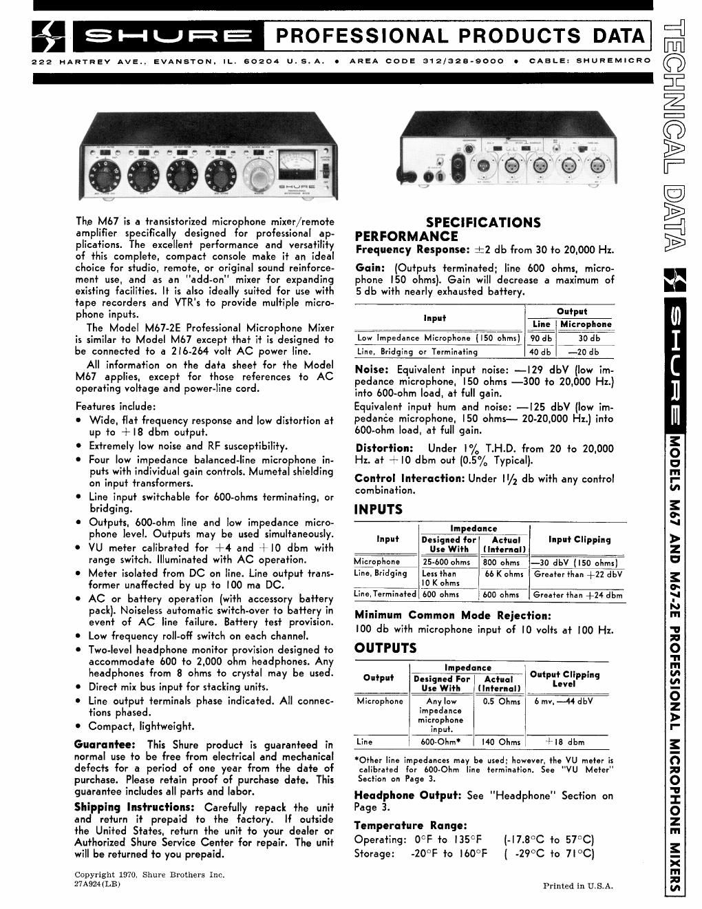
The M67 is a transistorized microphone mixer/remote
amplifier specifically designed for professional ap-
plications. The excellent performance and versatility
of this complete. compact console make it an ideal
choice for studio. remote. or original sound reinforce-
ment use. and as an add-on" mixer for expanding
existing facilities. It is also ideally suited for use with
tape recorders and VTR's to provide multiple micro-
phone inputs.

The Model M67-2E Professional Microphone Mixer
is similar to Model M67 except that it is designed to
be connected to a 2|6-264 volt AC power line.

All information on the data sheet for the Model
M67 applies. except for those references to AC
operating voltage and power-line cord.

Features include:

0 Wide. flat frequency response and low distortion at
up to +|8 dbm output.

Extremely low noise and RF susceptibility.

0 Four low impedance balanced-line microphone in-
puts with individual gain controls. Mumetal shielding
on input transformers.

Line input switchable tor 600-ohms terminating. or
bridging.

C Outputs. boo-ohm line and low impedance micro-
phone level. Outputs may be used simultaneously.

0 VU meter calibrated for +4 and +10 dbm with
range switch. Illuminated with AC operation.

0 Meter isolated from DC on line. Lina output trans-
former unaffected by up to too ma DC.

0 AC or battery operation (with accessory battery
paclr). Noiseless automatic switch-over to battery in
event of AC line failure. Battery test provision.

0 Low frequency roll-off switch on each channel.

0 Two-level headphone monitor rovision designed to
accommodate 600 to 2.000 ohm headphones. Any
headphones from 8 ohms to crystal may be used.

0 Direct mix bus input for stacking units.

' Line output terminals phase indicated. All connec-
tions phased.

0 Compact. lightweight.

Guarantee: This Shure product is guaranteed in
normal use to be free from electrical and mechanical
detects tor a period of one year from the date of
purchase. Please retain proof of purchase date. This
guarantee includes all parts and labor.

Shipping Instructions: Carefully repack the unit
and return it prepaid to the factory. It outside
the United States. return the unit to your dealer or
Authorized Shura Service Center for repair. The unit
will be returned to you prepaid.

Copyright 1970. Shure Brothers Inc.
27A924(LB)

AREA CODE 312/329-9000 I CABLE: SHUREMICRO

'5? ."i- fi .
,gl'e'ee Q

SPECIFICATIONS
PERFORMANCE
Frequency Response: :2 db from 30 to 20.000 Hz.

Gain: (Outputs terminated; line 600 ohms. micro-
phone l50 ohms). Gain will decrease a maximum ot
5 db with nearly exhausted battery.

Output
Input Line Microphone
Law Impedance Microphone (I50 ohms) 90 db 30 db
Line. Bridging or Terminating 40 db -zodb

Noise: Equivalent input noise: -|29 de (low im-
pedance microphone. ISO ohms -300 to 20,000 Hz.)
into bOO-ohm load. at full gain.

Equivalent input hum and noise: --l25 de (low im-
pedance microphone. |50 ohms- 20-20.000 Hz.) into
bOO-ohm load. at full gain.

Distortion: Under PA, T.H.D. from 20 to 20.000
H1. at + IO dbm out [0.5% Typical).

Control Interaction: Under /2 db with any control
combination.

IN PUTS
Impedance
Input Designed for Actual Input Clipping
Use With (Internal) 7
Microphone 25-600 ohms 800 ohms ~30 de ( ISO ohms)
Lino. Bridging Less than 56 K ohms Greater than +22 de
10 K ohms
Line. Terminated 600 ohms 600 ohms Greater than +24 dbm

Minimum Common Mode Rejection:
IOO db with microphone input of [0 volts at IOO Hz.

OUTPUTS

lmpedanELiv O t CI ,
°"'P'" Designed For Actual u Liv :pplng

Ulewith (IntfluIL ° ,7
Microphone Any low 0.5 Ohms 6 my. --44 de

impedance

microphone

input. l

Line boo-ohm l 140 Ohms +Is dbm

Other line impedances may be used: however. the VU meter is
calibrated for 600-Ohm line termination. See "VU Meter"
Section on Page 3.

Headphone Output: See "Headphone" Section on
Page 3.

Temperature Range:
Operating: O°F to l35°F
Storage: -20°F to |60°F

(-I7.8°C +0 57°C)
( .2900 to we)

Printed in U.S.A.

suaxrw anonaouorw 1vuorssaaoua az-mw um um gamma WILLWG TWQHNLEHQEi

Page 2

Overall Dimensions: See Figure "A"

- II%(288.9mm)

#6373207? mm) M

2+ (I27 m m)-* "L

000 00 oo oo o)-0
m

63
o

J

l
l
2?
(63.5mm)

l

" L_.

.i(6.4mm)-l

OVERALL DIMENSIONS -- FIGURE A

Overload and Shor'l'ing Profecl-ion:

Sh0r+ing +he ou+pu+s, even for prolonged periods. will
produce no damage.

Microphone inpu+s will no+ be damaged by signals. of
up +0 3 v0l+s (l00 +imes clipping level).

Operafing Vol'l'age:
MODEL M67:
AC Opera+ion: l20 vol+s. :|:l0°/o a+ 50 +0 60 Hz.

DC Opera+ion: 30 vol+s. 6 ma. maximum drain for
+ l0 dbm ou+pu+.

MODEL M67-2E:
AC Opera+i0n: 240 vol+s. ilOVo a+ 50 +0 60 Hz.

DC Opera+i0n: 30 vol+s. 6 ma. maximum drain for
+|0 dbm ou+pu+.

The Model M67-2E is supplied wi+h a +hree-conduc-
+or power-line cord. bu+ no plug. The power-line cord
plug should be ins+alled by 'a qualified person. The
brown lead should be connecfed +0 +he "live" or "ho+"
+erminal 0+ +he plug. and +he blue lead +0 +he neu+ral
+erminal 0+ +he plug. The green/yellow lead is +he
grounding conduc+or and should be connec+ed +0 +he
ground or ear+h +erminal 0+ +he plug.

Weighl': 4 lbs... l3 oz.

CONTROLS. CONNECTIONS

INPUTS AND OPERATIONS

Microphone:
The four microphone inpu+s. are professional female
+hree-pin audio connec+ors loca+ed on +he rear panel
and designa+ed "Mic. I" +hrough "Mic. 4." T
lnpu+s are balanced (in+erna| +rans+0rmer. mume+al
shielded) and connec+i0ns are Pins 2 and 3 "ho+.ll Pin |
"ground.'l
For microphone 0pera+i0n. +he swi+ches labeled
"Mic. l/Tone Osc. and "Mic. 4/Line" musl' be in
+he "Mic. I or "Mic. 4" posi+ion.
For impedance and clipping level see Table under
lnpu+ Specificafions.

Line:
The "Mic. 4" connec+or is also used as. +he Line lnpu+
Connecior by swi+ching +he "Mic. 4/Line" swi+ch +0
"Line."
Provision is made for ei+her 600-ohm line +ermina+i0n
or bridging. +he choice being made by +he appro-
pria+e posi+ion 0+ +he "Bridge/Terminal'e" swi+ch
above +he inpu+ connec+or.
Ei+her configura+ion is balanced and connec+ions are

TDesigned +0 rna+e wi+h Cannon XL series. Swi+chcrai+ A3 (QHG)
series or equivalenf connector.

Pins 2 and 3 llho+" and Pin l "ground."

lmpedances and 0pera+ing signal levels are shown in
+he "lnpul' Specificaiions" Secl'ion.

OUTPUTS

Microphone:
The micr0phone level ou+pu+ is a professional male
+hree-pin audio connec+0r l0ca+ed on +he rear panel
wi+h +he designa+ion "Mic. Ou+pu+."+ H is used for
feeding a low impedance microphone line or +he low
impedance microphone inpu+ of an associa+ed piece
0+ equipmen+. This is a balanced ou+pu+ wi+h Pin l
"ground." Pins 2 and 3 are "hot" and are in phase
wi+h +he corresponding pins of +he inpu+ connec+ors.

Line:
The line ou+pu+ (binding pos.+s) appears on +he rear
panel and is designa+ed IILine Ou+." These +erminals
are numbered "3" and "2 and are in phase wi+h cor-
respondingly numbered pins in +he inpu+ connec+ors.
The adiacen+ ground +erminal corresponds +0 Pin l.
While +he line ou+pu+ may be used +0 drive lines. of
various impedances. +he VU me+er is calibra+ed for
use wi+h a 600-0hm +ermina+ed line.
The line ou+pu+ +rans+ormer will opera+e properly wi+h
up +0 I00 ma. DC flowing +hrough +he line. This fea-
+ure allows use of ordinary dialed-up" +elephone lines
wi+h DC across +hem. (Since a sligh+ increase in dis-
+or+ion may occur a+ high ou+pu+ levels wi+h maximum
DC curren+. opera+ion a+ +4 dbm is recommended for
+his use.)
NOTE: The microphone and line 0u+pu+s may be used
simul+ane0usly if desired. +0 provide an isola+ed PA
feed or +0 drive differen+ pieces of equipmen+.

CONTROLS

Individual Inpu'l' Gain Conl-rols:
Froni' panel c0n+rols designa+ed nMic. l'l +hrough
"Mic. 4" are +he individual gain con+rols for corres-
pondingly numbered inpuis. N0+e +ha+ +he inpu+ con-
nec+ors are loca+ed 0n +he rear panel direc+ly behind
+heir corresponding numbered con+rol.
C0n+rol I"Mic. l" serves an addi+ional +unc+ion as +he
individual level con+rol for +he +one oscillaror when +he
"Mic. l/Tone Osc." swi+ch is in +he "Tone Osc."
posi+i0n.
C0n+rol "Mic. 4" also serves. as +he individual gain
c0n+r0l for +he line inpu+ when +he "Mic. 4/Line"
swi+ch is in +he "Line'I posiiion.

NOTE: For bes+ signal-+o-noise ra+i0. +he individual
inpu+ con+r0ls. should be 0pera+ed a+ as high
a se++ing as possible. consis+en+ wi+h main-
+aining adequa+e c0n+ro| range.