Shure m66 owners manual

This is the 2 pages manual for shure m66 owners manual.
Read or download the pdf for free. If you want to contribute, please mail your pdfs to info@audioservicemanuals.com.

Page: 1 / 2
left right
shure m66 owners manual

Extracted text from shure m66 owners manual (Ocr-read)


Page 1

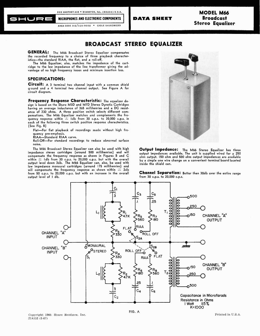
Output Level: Approximately -67dbm using Shure M3D or M7D Stereo Dynetic Cartridge from the RCA Test Record No. 12-5-71A. (Output measured with 250 ohm output impedance.) Insertion LOSS: 28db measured with conditions as outlined in "output level." The insertion loss may vary with different output load impedances. Hum Shielding: The M66 Equalizer is enclosed in an especially designed steel case for maximum shielding. Physical Size: The Equalizer case is 3%" wide, 3" high, and 5%" deep. The panel plate is 5" wide and 35/16" high. INSTALLATION: The Model M66 Broadcast Stereo Equalizer is designed to be mounted on a control panel with the switch shafts coming through the an el or to be mounted on a bracket, (supplied), for permanent installation where the switch shafts need not be accessible. The following steps are recommended for mounting to a con- trol panel. I. Using the panel plate of the Equalizer as a template, locate and mark the 2 mounting screw clearance holes and the 2 switch shaft clearance holes. 2. Drill 3/16 diameter holes to clear the mounting screws and 25/64 diameter holes to clear switch shafts. 3. Mount equalizer case and panel plate to the panel using the #8-32 machine screws. In this case, use the angle bracket as a spacer between the equalizer case and the panel. This allows clearance for the switch mounting nuts. 4. Cut switch shafts to proper length and install switch knobs. +10 e 24 : .PO LO W LT W 2 +lo % Y 0 20 M 90 8,000 5POO IOPOO a0W FREQUENCY IN CYCLES PER SECOND COMPENSATED FREQUENCYRESPONSE FIG. B CONNECTIONS: The Model M66 Equalizer is designed for use with a balanced line output or with an unbalanced line output. For a balanced line output connection, the "high" side of the line should be connected to the terminal marked + and the "low" side of the line should be connected to the adiacent "out" terminal (not coded). The shield or ground should be connected to the terminal marked GND. For an unbalanced line,output connection, the "high" side of the line should be connectdd to the OUT terminal marked + and the ground side of the line should be connected to both the ad- jacent OUT terminal and the GND terminal. If a separate shield is used, this may, also, be connected to the GND terminal. The two channel input (terminals marked IN) has a common ground, as indicated on the terminal board. In the "MONO" switch position, the two channel inputs are shorted together for monaural operation. GUARANTEE: This Shure Broadcast Stereo Equalizer is guar- teed to be free from electrical and mechanical defects for a period of one year from date of shipment from the factory, provided all instructions are complied with fully. In case of damage, it is es- sential that you carefully repack the unit and return it to the fac- tory for repair. Our guarantee is voided if the basic assembly has been subiected to unreasonably rough handling. FREQUENCY IN CYCLES PER SECOND FREQUENCY RESPONSE FIG. C