Shure m615as owners manual

This is the 16 pages manual for shure m615as owners manual.
Read or download the pdf for free. If you want to contribute, please mail your pdfs to info@audioservicemanuals.com.

Page: 1 / 16
left right
shure m615as owners manual

Extracted text from shure m615as owners manual (Ocr-read)


Page 1

PINK NOISE GENERATOR Output Level (Level control at 10) AUX LEVEL HI-Z MIC LEVEL LO-Z MIC LEVEL - 1 dBV (890 mV) -29 dBV (35 mV) -49 dBV (3.5 mV) Spectrum Equal energy per octave pink noise, flat %I dB, 32 Hz to 16 kHz lmpedance OUTPUT DESIGNED FOR USE WITH ACTUAL Lo-Imp. Mic Level 25- to 600-ohm microphone 110 ohms circuits balanced ABOVE 1 kHz ROLLOFF Hi-Imp. FREQUENCY RESPONSE Mic Level 33-kilohm microphone circuits 2.3 kilohms unbalanced FIGURE 2 Aux Level High-impedance (10 kilohms 1.5 kilohms or more) unbalanced aux unbalanced circuits Mic Overload ANALYZER (Pink noise levels to turn on MIC OVERLOAD LED) Sensitivity INPUT 15 d~ INPUT VOLTAGE SOUND ATTENUATOR PRESSURE USING (Pink noise levels to turn off LO LEDs; INPUT LEVEL ~~615 MICROPHONE control fully clockwise) LO-imp. Mic. out -40 ~BV (10 mv) 122 d~ SPL In -25 dBV (56 mV) 137 dB SPL INPUT 15 dB INPUT VOLTAGE SOUND Hi-Imp. Mic. Out -17 dBV (0.14V) - ATTENUATOR PRESSURE USING In - 2 dBV (0.79V) - ES615 MICROPHONE Lo-Imp. Mic. Out -117 dBV (1.4 pV) 45 dB SPL In - 102 dBV (8 pV) 60 dB SPL Hi-Imp. Mic. Out - 92 d BV (25 pV) - In -77 dBV (0.14 mV) - AUX - - 62 dBV (0.79 mV) - FlatlES615 Switch In ES615 position, complements low-frequency rolloff characteristic of ES615 Microphone (see Figure 1) t20 m +I0 z W V) 5 % 0 Y W E -10 Y -20 20 50 100 500 FREQUENCY IN HERTZ ES615/M615 SYSTEM LOW FREQUENCY RESPONSE FIGURE 1 Above 1 kHz Switch FLAT: Used for near-field measurements; produces flat resultant frequency response. ROLLOFF: Used for reverberant and far-field meas- urements; produces resultant frequency response rolled off at 3 dB per octave above 1 kHz (see Figure 2) lnput Overload (Pink noise aux input level to turn on INPUT OVERLOAD LED; INPUT LEVEL control fully clockwise) -25 dBV (56 mV) HiILo Envelope 2 to 12 dB (-+I to k6 dB), adjustable Aux Output Voltage Gain INPUT GAIN - Lo-Imp. Mic +54 dB** Hi-Imp. Mic +31 dB** AUX -4 dB '* lnput attenuator out Impedance INPUT DESIGNED FOR USE WITH ACTUAL - Lo-Imp. Mic. 25- to 600-ohm microphones 950 ohms balanced Hi-Imp. Mic. 33-kilohm microphones 140 kilohms unbalanced Aux 100-ohm to 10 kilohms high 42 kilohms unbalanced level sources OUTPUT DESIGNED FOR USE WITH ACTUAL Aux High-impedance (10 kilohms 4.7 kilohms unbalanced or more) unbalanced aux (with MIC input in use) circuits Operating Voltage M615: 108-132 Vac, 50/60 Hz, 5W M615-2E: 90-125 or 180-250 Vac, 50/60 Hz, 5W Temperature Range Operating: -7" to 57°C (20" to 135°F) Storage: -29" to 71°C (-20" to 160°F) Dimensions See Figure 3

Page 2

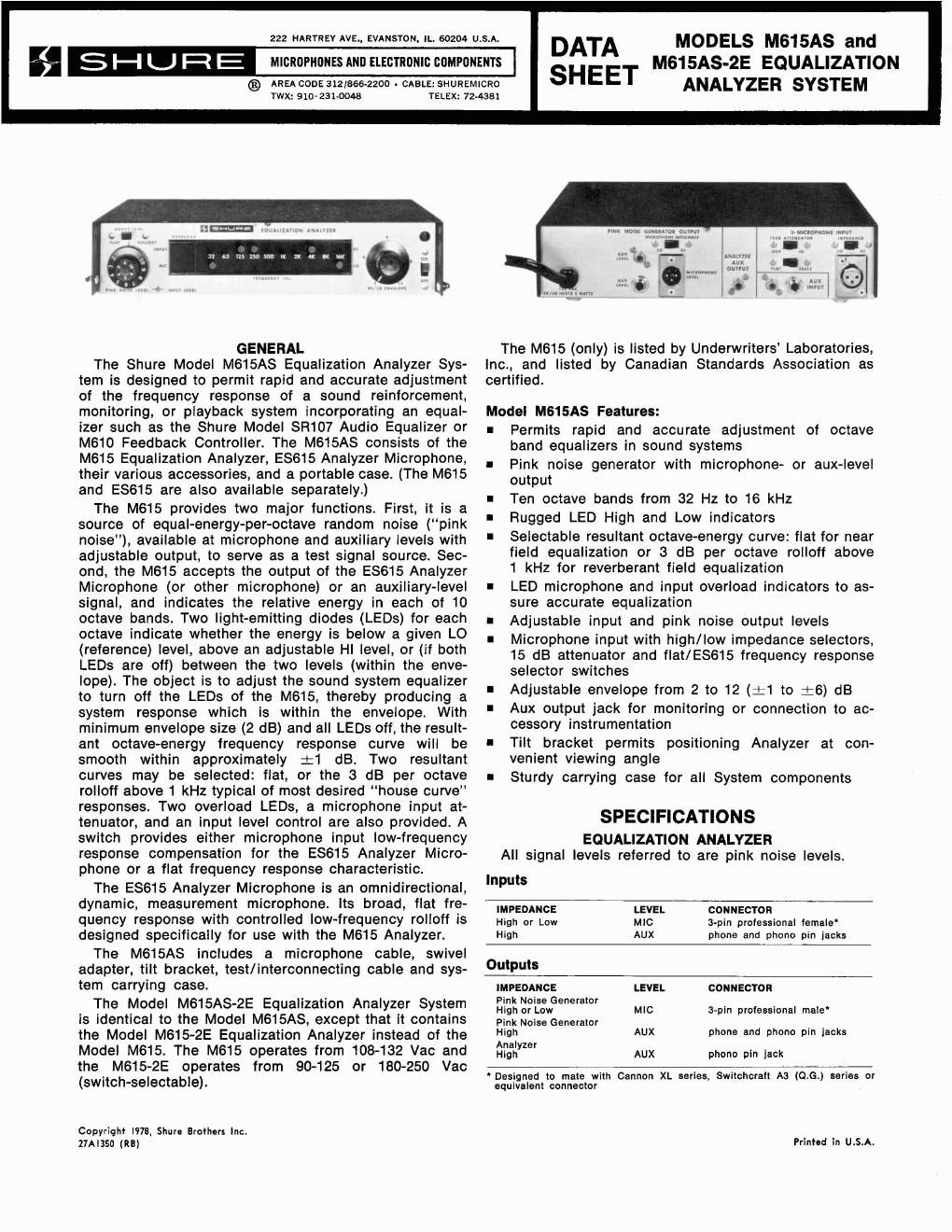
OVERALL DIMENSIONS FIGURE 3 Weight M615 M615AS Net 2.2 kg (4 Ib 13 oz) Combined Net 2.3 kg (4 Ib 15 oz) 5 kg (11 Ib) Packaged 2.9 kg (6 Ib 7 oz) 5.6 kg (12 Ib 4 02) CONTROLS AND CONNECTORS PlNK NOISE LEVEL Control: Sets pink noise generator output level. INPUT LEVEL Control: Sets input signal level and LO LED threshold to the analyzer. ABOVE 1 KHz Switch: Selects either a flat resultant high-frequency response or a smooth resultant high- frequency 3 dB per octave rolloff above 1 kHz. INPUT OVERLOAD LED: Lights if INPUT LEVEL control is set too high for input signal level, causing erroneous M615 LED indications. MIC OVERLOAD LED: Lights with excessive micro- phone input levels, indicating need to switch in 15 dB attenuator or reduce pink noise level. HI/LO ENVELOPE Control: Adjusts the HI LED threshold relative to the LO LED threshold. The resultant fre- quency response envelope may be varied from 2 to 12 dB (%I to +6 dB). HIILO LEDs: The LO LED for each octave lights if the input signal within its octave is below the lower thresh- old set by the INPUT LEVEL control. The HI LED for each octave lights if the input signal is above the upper threshold set by the HI/LO ENVELOPE control. PlNK NOISE GENERATOR OUTPUT - AUX LEVEL Con- nector: Provides pink noise generator output connec- tion to aux-level inputs. PlNK NOISE GENERATOR OUTPUT - MIC LEVEL Con- nector: Provides pink noise generator output connec- tion to microphone-level inputs. PlNK NOISE GENERATOR OUTPUT - MICROPHONE MI- PEDANCE Switch: Selects low- or high-impedance pink noise generator microphone-level output. MICROPHONE INPUT - 15 dB ATTENUATOR Switch: Reduces microphone input sensitivity to avoid micro- phone preamplifier overload. Affects microphone input only. MICROPHONE INPUT - FLATlES615 Switch: Selects either flat response or low-frequency boost comple- menting the response characteristics of the ES615 Analyzer Microphone, making the system response flat. Affects microphone input only. MICROPHONE INPUT Connector: Provides microphone input to analyzer. MICROPHONE INPUT - IMPEDANCE Switch: Selects low- or high-impedance microphone input to analyzer. AUX INPUT Connectors: Provides input to analyzer from mixers, amplifiers or other aux level input signals. In addition, accepts aux level output of pink noise gen- erator (using the supplied cable) for self-testing purposes. Automatically disables MICROPHONE INPUT if plug is inserted. AUX OUTPUT Connector: Provides for monitoring or connection to accessory instrumentation. This con- nector is in parallel with the analyzer AUX LEVEL input connectors, or monitors the equalized microphone pre- amplifier output if the AUX INPUT connectors are not in use. PRELIMINARY SETUP The following should be performed prior to using the M615AS Equalization Analyzer System: 1. Remove the protective cap from the grille assembly of the ES615 Analyzer Microphone. This cap should be used during transit and storage only. 2. Install the tilt bracket assembly on the M615 Equal- ization Analyzer as follows: Attach the No. 6-32 machine screws and capnuts in the two lower holes at the front of the M615 cover. Make certain the cap- nuts are on the outside of the cover. Insert the ends of the tilt bracket through the two upper holes at the front of the M615 cover. Slip the plastic caps over each end of the tilt bracket. Swing the tilt bracket downward against the front panel so that the machine screw heads provide a detent to stop the bracket from sliding (see Figure 4). Note that the M615 can be replaced in its carrying case with the tilt bracket in place and extending straight outward from the front panel. M615 WITH TILT BRACKET FIGURE 4 3. Model M615-2E: The Model M615-2E is supplied with a detachable line cord without a three-pin male power connector. Obtain a suitable three-pin male plug and attach it to the line cord. The plug should be installed by qualified service personnel. The brown lead goes to the "hot" or "live" terminal, the blue lead to the neutral terminal, and the green/yel- low lead to the ground or earth terminal. Select the proper voltage range (90-125 or 180-250 Vac) using the rear-panel VOLTAGE SELECTOR switch.