Shure ams880 owners manual

This is the 4 pages manual for shure ams880 owners manual.
Read or download the pdf for free. If you want to contribute, please mail your pdfs to info@audioservicemanuals.com.

Page: 1 / 4
left right
shure ams880 owners manual

Extracted text from shure ams880 owners manual (Ocr-read)


Page 1

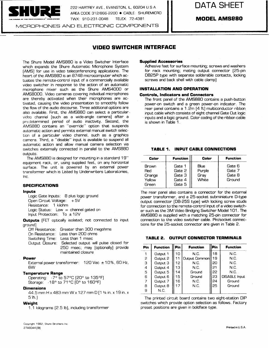
TABLE 3. OPTION SWITCH FUNCTIONS Switch 6 Station Function lnput T~rne Delay Autornat~c ldle Opt~on Automat~c ldle T~nie See Table 4 Select~on Rotat~on Rate O~sabled 2.7 sec Output Mode Ma~ntaned Pulsed Overr~de Channel 1 Enabled Disabled 53-2 Overr~de Channel 2 Enabled Disabled 53-3 Overr~de Channel 3 Enabled Disabled 53 4 Overr~de Channel 4 Enabled Disabled 53-5 Overr~de Channel 5 Enabled Disabled 53-6 Overr~de Channel 6 Enabled Disabled 53 7 Overr~de Channel 7 Enabled Disabled 53-8 Overr~de Channel 8 Enabled Disabled - - - -- - -- -- - *Off posltlon IS marked OPEN, On posltlon 1s not marked TABLE 4. AUTOMATIC IDLE CHANNEL SELECTION 152-8pFEJ+s2i4- Channel Off Off Off Off On On On On Off Off On On Off Off Un On Off On Off On Off On Off On Install the AMS88O as follows. I. lf any changes from the factory preset optlons are desired, remove the AMS880 cover and set option swit- ches [S2, S3] for the desired function [see tables 3 and 4 and explanations below]. Replace the cover. 2. Install the AMS880 in a standard 19-inch equipment rack [screws and washers are provided] or on a horizon- tal surface [protective feet are provided]. 3. Fabricate a connecting cable between the video switcher and the AMS880 using the supplied 25-pin DB25P type connector. Install the cable between the video switcher and the AMS880 output jack. 4. Connect the leads of the multiconductor lnput cable of the AMS880 to the Gate Out terminals of the AMS mixer follow~ng the EIA color coding [brown-Channel 1, red- Channel 2, etc. as shown in Table I]. Connect the AMS880 white input lead [Ground] to the Channel 8 [AMSBOOQ] or Channel 4 [AMS4000] Loglc Ground ter- minal of the AMS mixer. 5. Connect the external power transformer to . the AMS880. 6. Connect the power transformer to a 120 Vac, 60 Hz source. Operation With all equipment connected, turn the AMS880 on by depressing the Power sw~tch. If no funct~on options have been changed from their factory settings [using internal switches 52 and S3], a given camera channel will be selected after its AMS mixer channel has been on for 2.5 seconds. This input time delay prevents changing cameras if an AMS mlxer channel has been activated by a short sound such as brief paper rustllng or chair squeaking. Note that the time delay can be decreased from 2.5 to 1.9 seconds by movlng switch 52-1 to the "off" position. Dur~ng periods of inactivity, the last camera channel ac- tivated will remain on. It two or more AMS mixer channels are active s~multaneously, camera channel selection w~ll rotate among those among those channels at a rate of 2.7 seconds per channel. The rotatlon action can be disabled by movlng switch S2-7 to the "on" [non-OPEN] posit~on. Options Automatic ldle Opt~on Internal switches S2-2 through S2-6 are assigned to the automatic Idle channel function. When an automatlc Idle channel has been selected, cessation of activlty by the AMS mixer for more than 6.2 seconds will cause the autornatlc idle channel to be activated. This allows switching to a wide- angle or a graphics camera when no one IS talk~ng. Normal action is restored when any input is active for the selected Input time delay of 2.5 or 1.9 seconds. Switch 52-2 turns the automatic idle function on or off. Switch S2-3 chooses the automatic idle time delay of 6.2 or 8.8 seconds. Switches S2-4, S2-5 and S2-6 select, through a binary logic code system [see Table 41, the number of the channel selected for the automatic idle opera- tion. Overr~de Option Any or all input channels can he selected to overrlde the automatlc channel selectron funct~on nf the AMS mixer The selected override Inputs will usually be actrvated by a manual sw~tch closure to ground, rather than an AMS mixer gate output When S3-1 through 53-8 are enabled [turned on]. any overrlde lnput actlvated wlll take precedence over those channels normally actlvated by the AMS mlxer operation If more than one overr~de option channel 1s enabled, the f~rst Input actlvated will turn on Heleasrng all overrlde Input switch closures to ground w~ll restore automatic AMS m~xer-controlled actlon Disable Option An external switch closure from Output Connector pin 23 to pin 25 [Ground] will suspend all autornatic action, allowing any parallel-connected [external] switch closures between Output Connector Common [p~n 1 1 ] and Output Channels [pins 1 through 81 to control the vrdeo switcher's action. Releasing the Disable switch closure will immediately restore automatic action. GUARANTEE This Shure product IS guaranteed In normal use to be free from electrical and mechanical defects for a per~od of one year from date of purchase. Please retain proof of purchase date. This guarantee includes all parts and labor. This guarantee is in lieu of any and all other guarantees or war- ranties, express or implied, and there shall be no recovery for any conseq~jentlal or incidental damages. Carefully repack the unlt, insure ~t, and return ~t prepa~d to: Shure Brothers Incorporated Attention: Service Department 222 Hartrey Avenue Evanston, Illinois 60204 If outside the United States, return the unit to your dealer or Authorized Shure Service Center for repair. The unit will be returned to you prepaid.

Page 2

REPLACEMENT PARTS LIST Parts that are readily ava~lable through local electronic parts distributors are not shown on the Circuit Diagram. -- - -- Reference Designation - - C6 Dl-Dl 9, 021-036 Description -- ---- pp ppp - -. . . . Capacltor. Electrolytic. 47wF, 1 OV Capacltor, Electrolytic, 1000 {LF, 25V Capacltor, Electrolytic, 4 7 wF, I OV Dlode, Slllcon Computer. 75 mA, IOOV Diode. General Purpose Rectlfler, 1 A, 100V Dtode, L~ght-Emttt~ng. Green Dtode, Zener. Overvoltage Translent Suppressor Fuse 3AG. ' )A. 250V Connector, 25-Socket Transistor, NPN, General Purpose Varlstor Metal Oxide Swttch, Push-Button, Power, SPST Switch Assembly, Dual In-Line SPST Integrated Clrcult, Schmitt Trigger Inverter lntegrated Clrcult. Mtcrocomputer Reslstor Network Dpto-Isolator [Photon-Coupled Btlateral FET] Power Transformer. Prtrnary 120 Vac * 10%. 57-63 Hz, Secondary 22 Vac, 16 VA. CT, wtth cable and connector Voltage Regulator, Pos~tlve Fuseholder Crystal, Quartz 3 579545 MHz HC-1 8IW Holder -- - - - - - . -- - - shown on the following list. Their values are - - - - -- - - -- Manufacturer 6 Part Number -- p- -- Sprague 503D476FOlOLA Sprague 501 Dl 08F025QS Sprague 199D475X0010BB1 Motorola 1 N4002 Shure 86C8402 Motorola MPTE 5 Llttelfuse 31 2 500 AMP 206584-2 Shure 55A8013, 1TT NEI 51 F2U103EE/01-003-00 TI SN74LS14N Shure 86A8806. NEC pPD8748* Intel 8748' Bourns 431 OR-1 01RC1 K GE HIIF1 Shure 95A8048 Motorola MC7805CT Littelfuse 10207 1 GTE ECG358 - . . . - .- Programmed wtth operatlrig code PRINTED CIRCUIT BOARD - COMPONENT SIDE SOLDER SlDE