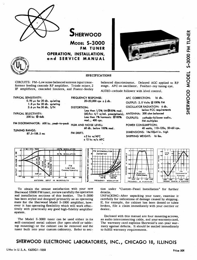
Sherwood s 3000 tun service manual

This is the 4 pages manual for Sherwood s 3000 tun service manual.
Read or download the pdf for free. If you want to contribute, please mail your pdfs to info@audioservicemanuals.com.

Page: 1 / 4
left right
Sherwood s 3000 tun service manual

Extracted text from Sherwood s 3000 tun service manual (Ocr-read)


Page 1

SHERWOOD

MODEL 5-3000
FM In NH!

OPERATION, INSTALLATION,
and SERVICE MANUAL

CIRCUITS: FM-Low noise balanced antenna input trans-
former feeding cascade RF amplifier. Triode mixer, 2
117 amplifiers, cascaded limiters, and Foster-Seeley

SPECIFICATIONS

balanced discriminator. Delayed AGC applied to RF
stage. AFC on oscillator. Feather-ray tuning eye.

AUDIO-cathode follower with level control.

SHERWOOD MODEL 5-3000 FM TUNER

TYPICAL SENSITIVITY: FREQUENCY RESPONSE: AFC COKRECTION: Io db.
0:): W I: :3 j: :2 2°"°'°°° I * I 5 outrun 2.0 van. @ 100% FM
315 5: I so At: 3N m msmmom OSCILLAYOR RADIATION: a db.
Leis rhun I/aas mamas Midi WW FCC "WWW
TYPICAL SELECTIVITY: (60/kc: 4/1 w/ud. pmnphum), ANTENNA: 300 ohm balanced
20° kc @465 lam than 1% hannoulc 01m outPuts: cathode-follower audio.
mat, 400 cps. FM multiplex
m DISCR'M'NAIOR 6 " °"'°l°°" HUM AND NOISE LEVEL: POWER CONSUMPTION:
was. below Im mod. to mm, IIo-Izm, 50-60 cm.
TUN'NG "gffim 5 m M mun. DIMENSIONS: 14x10 In. high
' ' :2 kc w/AFC SHIPPING WEIGHT: 16 lbs.

1 I5 kc w/o AFC

FM
meua
cumncrrmnrm

o
a
e
3
S
g.
o
3
A
.
>
a

an In

mun mour m IICIDVOLYI

at now-tunic m MM mama

To obtain the utmost satisfaction with your new
Sherwood $3000 FM tuner, review carefully the operation
and installation sections of this booklet. The 5-3000
has been styled and designed primarily as an operating

mate for the Sherwood Model 5-1000 amplifier, how-'

ever it has operating flexibility which will work effec-
tively with practically any good high-fidelity amplifier
system.

The Model 5-3000 tuner can be used either in its
self-contained metal cabinet (for open-shelf or table-
top mounting) or the cabinet can be removed and the
tuner built into your custom cabinetry. Refer to sec-

smegma

m nm-m

I \
I I
I

E
E
3

nun-s:

m . F
CSELKYNNV - DIunmmuaI
(Sign, (mum I'm? .I
. .
0," «on >Ioo a «w um .
FIEoumcv naouuvlnu mm," ,. WM, Wm mm mm.

tion under "Custom-Panel Installation" for further
details.

UNPACKING-After unpacking your tuner, examine it
carefully for indications of damage caused by shipping.
If. for example, the cabinet has been dented or tubes
broken, file a claim immediately with your carrier or
dealer.

Enclosed with this manual are {our mounting screws,
an audio interconnecting cable, and yourwarranty card.
The warranty card explains Sherwood's one-year war-
ranty against defects. It should be mailed immediately
to fulfill warranty requirements.

SHERWOOD ELECTRONIC LABORATORIES, INC., CHICAGO 18, ILLINOIS

Liiho in U.$.A. K620GI»I058

PrIOo 50¢

Page 2

INSTA LLATION

The 5-3000 tuner usually is located to provide the
greatest operating convenience--on a chairside table,
desk, bookshelf, or in a conventional radio cabinet. It
is recommended that tuner installations in the fringe
area of radio stations use external antennas. In this
case, the tuner should be located where it is accessible
to the antenna lead-in. Metropolitan or suburban in-
stallations can satisfacmrily use the built-in antennas
without need for antenna lead-in considerations. Up to
75 feet of shielded cable may separate the tuner and
amplifier for remote installations.

IMPORTANT-Allow at least 2 inches behind the rear
of your tuner for adequate ventilation and cabling con-
venience. Never place the unit near radiators or in
front of heating vents. Excessive heat tends to shorten
the life of the parts.

PANEL MOUNTING-The 5-3000 tuner is a self con-
tained, self»cabineted unit which is easily adapted for
panel mounting in custom cabinetry. The enclosed full-
size mounting template should be used for custom
installation.

To mount the Sherwood tuner behind a panel, first re-
move the two front control knobs with a steady outward
pull, Now unscrew the 4 machine screws holding the
metal cover. Remove cover and panel assembly by
sliding forward from chassis.

Disassemble the bezel from cover by unscrewing its 4
retaining screws. Remove the two L side brackets
from the front corners of the chassis. Fasten these
side brackets to the bezel (keeping front panel behind
bezel) using the screws that formerly held the bezel
to the cover. Slide bezel assembly over knobs and at»
tech brackets to chassis so that the panel is snug against
dial. Replace knobs.

Cut panel cutout 3-5/8 x 13-3/4 as shown on template.
Slide tuner through cutout from the front. The chassis
should be provided with either a shelf or rails to sup-
port its weight. Holes may be drilled as shown in the
supporting members to fasten chassis securely with
the mounting screws that are supplied.

ELE CTRJCAL CONNECTION 5

AUDIO OUTPUT - A shielded interconnecting cable
with phono plugs has been included as an accessory
with your tuner. This cable may be used to connect
the tuner with your amplifier. Insert one end firmly
into the jack labeled audio output (at the rear of the
tuner.) The other end should be plugged into a high-
level input such as those marked llA", B", or "C on
the Model 8-1000 amplifier. lnteroonnections may be
made up to 75 feet by using a similar-type shielded
cable.

FM ANTENNA - Connected to the FM antenna terminals
are two lengths of plastic covered wire. Unwrap these
wires and extend them in opposite directions and per-
pendicular to the direction of your smtion location.
For urban locations having good signal strength, the
antenna lead can be concealed by Scotch taping to the
line cord. To reduce noise, fading, or interference on
weak, distant stations, use a roof-top 300»ohm FM
antenna array and 300-ohm ribbon leadin. A some-
what less -effective antenna system can be built in the

attic from 5 feet of SOD-ohm TV lead-in. Split one side
of this lead and connect another piece of 3w.uhm lead-
in to serve as its lead in. Twist the two ends together
as shown in Fig. 1 and solder. Tack antenna perpendi-
cular to the direction of your station location. Best
performance will be indicated by the widest pattern on
the tuning eye.

Direct interconnection with a TV antenna lead is also
permissible. If interference from this interconnection
is suspected, a connection with less coupling may be
made by taping about 5 inches of the FM tuner 300-
ohm lead adjacent to the TV lead without actually mak»
ing a direct connection.

Although the FM antenna input is designed for 300»
ohm balanced input, a 70-ohm unbalanced cable may
be connected to one of the FM terminals and ground.

MULTIPLEX OUTPUT-This jack provides a non-de-
emphasized signal from the FM section at high im-
pedance for connection to a multiplex converter.
(Multiplex FM transmission, still in the developmental
stage, will provide 2 or 3 programs on one station.)

POWER CONNECTION-Plug the 5-3000 line cord intoa
wall outlet or amplifier power outlet supplying l 10. 120V,
504%] cycle AC only. Special models for 220-240 V
are clearly marked on the nameplate.

OPERATION

To operate, turn the left-hand knob clockwise; the
dial will then be lighted. Tune station for clearest
signal with tuning knob; the tuning eye will open widest
at the point of best tuning.

FM AFC SWITCH - Normal usage is with AFC "on
and allows the electronic automatic frequency control
to aid in tuning to the center or least-distorted point of
each FM station. In addition, AFC reduces any tendency
for the tuner to drift or detune away from a station.
Where a weak station is being tuned on achannel
adjacent to a much stronger station, the AFC may be
turned to off to prevent the stronger station from
pulling the tuning away from the desired weaker station.

LOCAL-DISTANT SWITCH - Normal operation is with
this switch in the Distant position. Where the tuner
is used near a powerful transmitter, the nearby station
might be noted to have several points throughout the
band where it can be heard. To suppress this effect
of multiple cross -modulation images (a characteristic
of all highly-sensitive FM receivers), switch to the
"meal position. lnthe Local position, the sensitivity
of the Model 5-3000 is reduced to 1/10 normal.

Should the local interference prevent reception of a
desired distant station in a manner not alleviated by
switching to Local", write the Sherwood Electronic
Lab. Service Dept. for information on an antenna filter
trap tuned to the interfering station.

AUDIO LEVEL CONTROL-A level control is provided
on the rear of the tuner chassis to regulate the audio
output signal level fed to the amplifier.