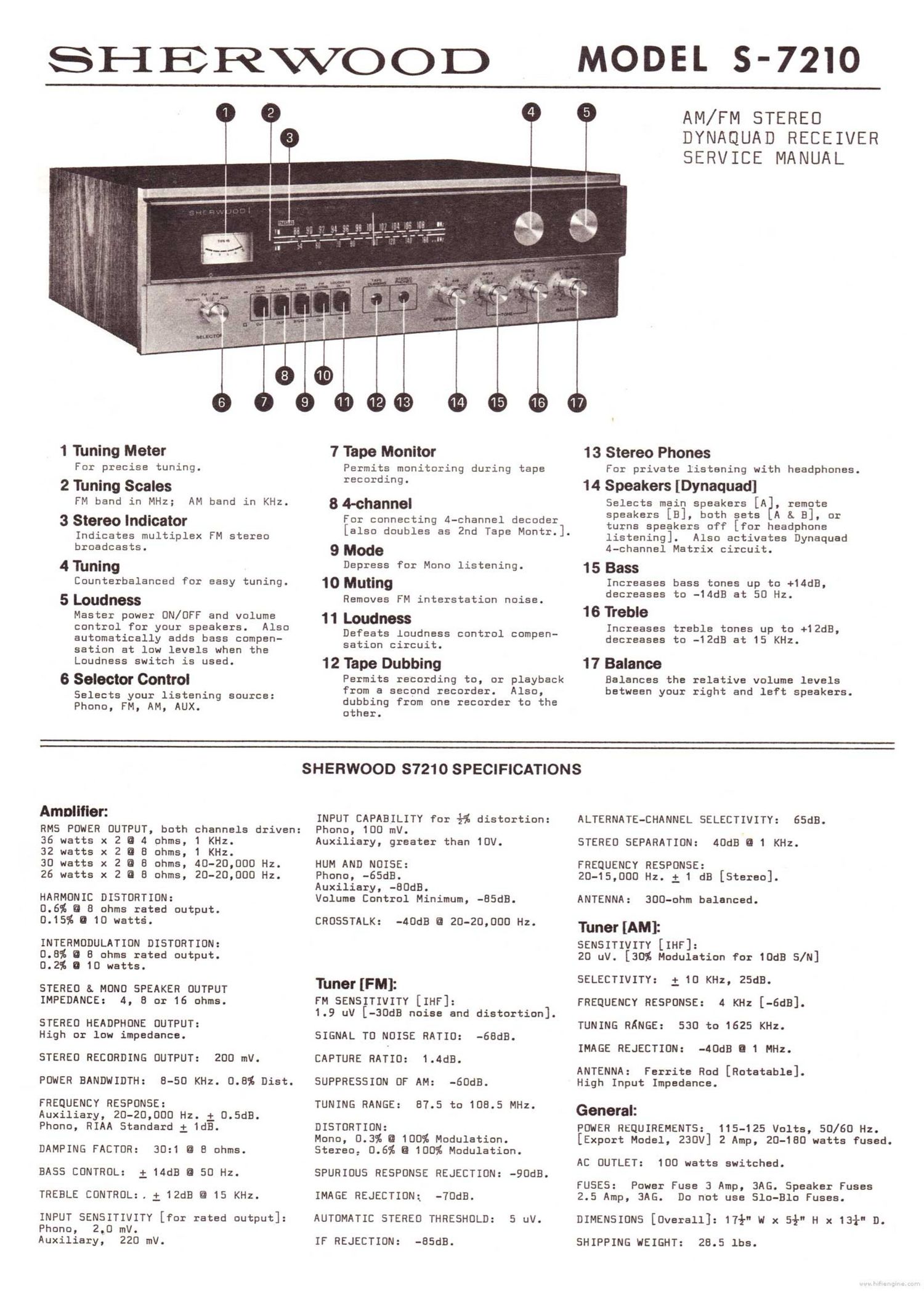
Sherwood S 7210 Service Manual

This is the 15 pages manual for Sherwood S 7210 Service Manual.
Read or download the pdf for free. If you want to contribute, please mail your pdfs to info@audioservicemanuals.com.

Page: 1 / 15
left right
Sherwood S 7210 Service Manual

Extracted text from Sherwood S 7210 Service Manual (Ocr-read)


Page 1

SHERWOOD

MODEL 5-7210

v.

Wuwtww-ASSILJV f "
-4 t .a- .. I
' _._ V -.

14 15 16

1 Tuning Meter

For precise tuning.

2 Tuning Scales
FM band in MHz;

3 Stereo Indicator

Indicates multiplex FM stereo

7 Tape Monitor

Permits monitoring during tape
recording.

8 4-channel

AM band in KHz.

broadcasts. 9 Mode

4Tuning Depress for Mono listening.
Counterbalanced for easy tuning. 10 muting

5 LOUdlIess Removes FM interstation noise.
Master power ON/OFF and volume 11 WHO

control for your speakers. Also
automatically adds bass compen-
sation at low levels when the
Loudness switch is used.

6 Selector Control

Selects your listening source:
Phono, FM, AM, AUX.

sation circuit.

12 Tape Dubbing

from a second recorder. Also,

other.

For connecting 4-channel decoder
[also doubles as 2nd Tape Montr.].

Defeats loudness control compen-

Permits recording to, or playback

dubbing from one recorder to the

AM/FM STEREO
OYNAQUAO RECEIVER
SERVICE MANUAL

17

13 Stereo Phones

For private listening with headphones.

1 4 Speakers [Dynaquad]

Selects main speakers [A3, remote
speakers [B], both sets A & B], or
turns speakers off [for headphone
listening]. Also activates Dynaquad
4-channel Matrix circuit.

15 Bass

Increases bass tones up to +14dB,
decreases to -14dB at 50 Hz.

1 6 Treble

Increases treble tones up to +12dB,
decreases to -12dB at 15 KHz.

1 7 Balance

Balances the relative volume levels
between your right and left speakers.

SHERWOOD S7210 SPECIFICATIONS

Amplifier:

RMS POWER OUTPUT, both channels driven:
36 watts x 2 O 4 ohms, 1 KHz.

32 watts x 2 fl 8 ohms, 1 KHz.

30 watts x 2 fl 8 ohms, 40-20,000 Hz.

26 watts x 8 ohms, 20-20,000 Hz.

INPUT CAPABILITY for %% distortion:
Phono, 100 mV.
Auxiliary, greater than 10V.

HUM AND NOISE:

Phono, -65dB.

Auxiliary, -80dB.

HARMONIC DISTORTION: Volume Control Minimum, -85dB.

0.6% fl 8 ohms rated output.

0.15% a 10 watts. CROSSTALK: -40dB a 20-20.000 Hz.
INTERMOOULATION DISTORTION:
0.8% 0 8 ohms rated output.
0.2% O 10 watts.
STEREO s. MONO SPEAKER OUTPUT Tuner [PM]:
IMPEDANCE: 4, a or 16 ohms. FM SENSITIVITY [IHF]:
1.9 uV [-30dB noise and distortion].
STEREO HEADPHONE OUTPUT:
High or low impedance. SIGNAL T0 NOISE RATIO: -68dB.
STEREO RECORDING OUTPUT: 200 mV. CAPTURE RATIO: 1.4dB.
POUER BANONIDTH: O-SO KHz. 0.8% Dist. SUPPRESSION OF AM: -60dB.

FREQUENCY RESPONSE:
Auxiliary, 20-20,000 Hz. 1 0.5dB.
Phono, RIAA Standard i 1dB.

TUNING RANGE: 07.5 to 108.5 MHz.

DISTURTIUN:
Mono, 0.3% a 100% Modulation.

DAMPING FACTOR: 30:1 8 8 ohms. Stereo, 0.6% a 100% Modulation.

BASS CONTROL: i 14dB Q 50 Hz. SPURIOUS RESPONSE REJECTION: -90dB.

TREBLE CONTROL:. 1 12dB E 15 KHz. IMAGE REJECTION: -70dB.

INPUT SENSITIVITY [for rated output]: AUTOMATIC STEREO THRESHOLD: 5 uV.
Phono, 2.0 mV.
Auxiliary, 220 mV.

IF REJECTION: -85dB.

ALTERNATE-CHANNEL SELECTIVITY: 65dB.

STEREO SEPARATION: 40dB fl 1 KHz.

FREQUENCY RESPONSE:
20-15,000 Hz. 1 1 dB [Stereo].

ANTENNA:

Tuner [AM]:

SENSITIVITY [IHF]:
20 uV. [30% Modulation for IOdB S/N]

300-ohm balanced.

SELECTIVITY: i 10 KHz, ZSdB.

FREQUENCY RESPONSE: 4 KHz [-6dB].
TUNING RANGE: 530 to 1625 KHz.
IMAGE REJECTION: -40dB a 1 MHz.

ANTENNA: Ferrite Rod [Rotetable].
High Input Impedance.

General:

PONER REQUIREMENTS: 115-125 Volts, 50/60 Hz.
[Export Model, 230v] 2 Amp, 20-180 watts fused.
AC OUTLET: 100 watts switched.

FUSES: Power Fuse 3 Amp, 3AG. Speaker Fuses
2.5 Amp, BAG. Do not use Slo-Blo Fuses.

DIMENSIONS [Overall]: 17%" w x 5% H x 13+n D.

SHIPPING HEIGHT: 23.5 lbs.

Page 2

Sherwood Service Manual MODEL 5-7210

RECEIVER SERVICE EEORMAEON

CONTENTS: PAGE:
PARTS LOCATIONS [Figure 1] Inside Covers
AMPLIFIER SERVICING AND ADJUSTMENT' 1
POWER SUPPLY SERVICING 4
FM TUNER AND IF ALIGNMENT 4
MULTIPLEX ALIGNMENT 5
AM TUNER AND IF ALIGNMENT 6
MECHANICAL DETAILS 6

Push-Button Repair 6
Dial Stringing 7
ORDERING PARTS B

PARTS LIST [See Supplements]

SCHEMATIC DIAGRAM [See Supplements]

AMPLIFIER SERVICING AND ADJUSTMENT

NOTE:

For simplicity, only the left channel and its related circuitry are described. The right
channel is identical except for reference symbol numbers [see Schematic Diagram]. For
parts locations, refer to Figure 1 on the inside covers.

USE OF A VARIAC:

It is imperative that a variable voltage line source [Variac] equiped with a line watt-
meter to identify abnormal power consumption be used when servicing power amplifiers and
associated power supply circuitry. With the Loudness volume control set at minimum, the
power consumption should not exceed 20 watts as the voltage is increased by the Variac to
the rated 120 VAC. If the power consumption begins to exceed 20 watts, do NOT increase
the line voltage any further. Determine if the malfunction is in the power supply, tuner
or amplifier section of the receiver.

SPEAKER FUSE ANQ__SPEAKER S_§TEfl CHECK:

The 5-7210 incorporates a speaker protection fuse in each channel. Verify that both fuses
are unopened and that both speaker systems and their associated wiring are short-free.

LINE FUSE AND INITIAL CIRCUIT CHECKS:
Verify that the line fuse is unopened and check idling power consumption. The main causes
for abnormal power consumption, in order of decreasing occurance, are:
1. Open or shorted amplifier output, driver or pre-driver transistors [TR601-610].
2. Open or shorted power supply diodes [DBO1-804].
3. Shorted power transformer.
NOTE:

For the following tests, an 8 ohm load resistor must be connected to each of the two
power amplifier (speaker) output terminals.

- 1 _