Sherwood S 5500 II Service Manual

This is the 11 pages manual for Sherwood S 5500 II Service Manual.
Read or download the pdf for free. If you want to contribute, please mail your pdfs to info@audioservicemanuals.com.

Page: 1 / 11
left right
Sherwood S 5500 II Service Manual

Extracted text from Sherwood S 5500 II Service Manual (Ocr-read)


Page 1

SHERWOOD
MODEL 5-550011 - 64 WATT
STEREO DUAL AMPLIFIER-PREAMPLIFIER

OPERATION, INSTAlLATION,
' and SERVICE MANUAL

thr _1

With your purchase of Sherwood High Fidelity
equipment, you join an ever-increasing group of proud
Sherwood owners. To increase your appreciation of
the many operating and performance features designed
into every Sherwood product, this operating manual
has been prepared. We urge you to read the entire
manual carefully in order that you may benefit from

1-

Although many operating refinements have been in-
cluded which initially may not seem essential to the
operation of your equipment, tmther experience in
good hatching invariably results in your appreciation
of these refinements provided by Sherwood. Conse-
quently, we suggest you savethismanual for reference

these features.

to the valuable information contained herein.

SEE PAGE 5 FOR SIMPLHED HOOKUP & OPERATING PROCEDURE!

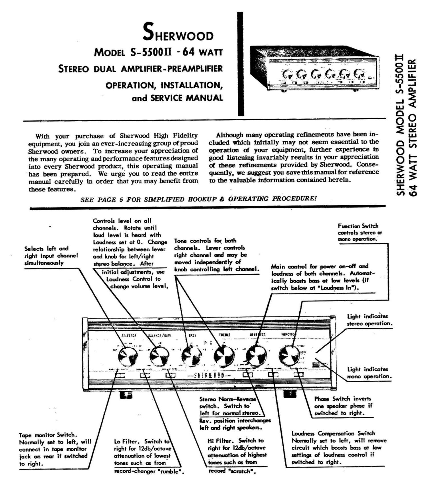
Selects left and
right input channel
simultaneously

Tape mnitot Switch.
Nor-molly set to left, wi
connect in tqae monitor
jack on rear if switched
to right.

IT

Controls level on all
channels. Rotate until
loud level is heard with
Loudness set at 0. Change
telntiomhip between lever
and knob for left/right
stereo balance. After
initial odiustments, uoa
[undress Control to
change volume level.

Tone controls for both
channels. lever controls
tight chormeI ad my be
moved independently of

limb controlling left choml.

Function Switch
controls stereo or
none operation.

Main control for power on-off turd
loudness of both chonnek. Anton-It-
icolly boasts boo at low levels (if
switch below at 'Loutlnes ln').

ll lo Filter. Switch to
right for lZdb/octove
attenuation of lowest

tones such as from

Stereo Norm-Reverse
switch. Switch to'

left for nonmlsteroo.
Rev. position interchanges
left and tidtt speakers.

Hi Filter. Switch to
tidtt for erb/octove
win of highest
tones arch as from

ROOM-Zimmer 'mle',

(econ! scrutch'.

.9 - _ Lidtt when:
._...._- wk l stereo operation.
if sumo: 'un-zr/una ms me: an 33 mm I
r ,_ "If. . -' .5 g t -- - - .. .-__.._.,_..._ h - I
" 4 l' " i .. J l:
V l . . h... 5
, ..
-__-.'. we -- :- w .. "3- .__...';~ -- -::-..t':~.- ---.~_.V..t-- Light irdiootes
I l- -§H[nufiflp_. I. I .

mono operation.

Phase Switch inverts

one speaker phase if
switched to right.

Loudnea Commotion Switch
ltlorrnolly set to left, will retrieve
circuit which boosts boss at low
setting of loudness control if
switched to right.

SHERWOOD MODEL S-SSOOII
64 WATT STEREO AMPLIFIER

Page 2

MODEL S-55t

INPUTS:
6 high level, 2 (RIAA) Phono-preunp,
2 (NAB) tapehead preamp. '

POWER OUTPUT:
Stereo: eac'e. channel 32 watts
music power (24 watts continuous,
48 watts peak) or Mono: 64 watts
music power (48 watts continuous,
96 watts eolr) C "5% IM distortion

FREQUENCY RESPONSE:
(24 w) 20 cpsta 20 Irc :I db.

TONE CONTROL RESPONSE:
Flat setting,20 cps to I) Ir: :1 db.

TONE CONTROL RANGE:
I5 Irc, I7 db. boost or cut.
40 cps. I6 db. boost or cut.

JSTEREO AMPLIFIER SPECIFICATIONS

MAX. HUM 8. NOISE:
Vol. control min.,90 db. (weighted)
below rated output.
Radio input (controls max.),85 db.
(weighted) below rated output.
Phono input (controls flat), 60 db.
below rated output, 72 db. below
IOInv (equivalent to )9 pv referred
to input grid).

(60cz7kc 4:1). LOW FILTER: INTERCHANN EL CROSSTALK:
20 cps, 20 db. reiection; 60 cps less Less than ~50 db. 9 I he.
OUTPUTS: than I db. dawn.
I6, 8, and 4-ohm left and right speaker; POWER CONSUMPTION:
2 recording. PREAMP. EQUALIZER CURVES: IIO-IZOV, 60 cps, I40 watts fused.
AES/RIAA phone and NAB tape.
INVERSE FEEDBACK: TUBE COMPLEMENT:
I4 db. SENSITIVITY: (4) 7868, (5) I2AX7/EC03,
Radio 0.3V. 4 silicon rectiliers
DAMPING FACTOR: Phone Lbnv. Two head: I.6mv.
5:I (all inputs adjustable with gain control). SIZE:
I4xI3tix4 in. high
MAX. INPUT CAPABILITY:
Phone: 200m. for less than 1% dist. SHIPPING WEIGHT:
Radio: Adiustable with pain control. 25 lbs.

OUTPUT N HTTS (PEAKI

2 4 IO 20 40 I)
I I "
__ s-ssoan
ACH CI'IA
3 -§s mm",mw l mm in crass ran secure
3 zoaoiooaaaaaomairsslanaanaanraan
9.: f l
8 a .5
9 We DiS'lORTtON
° we rowan g
3' m1 mammal! g
' " orsrannou 1* w
[race/null) °
i
J
o " "' ,
I 2 s to 20 40
oumn m WATTS (Rust
GENERAL INFORMATION be located within ten feet of your amplifier's input panel.

Your new Sherwood amplifier affords you with the full-
est enjoyment possible in the field of true high fidelity.
Though simple to operate, it has many operating features
permitting the utmost in listening pleasure in any situa:
tion. It is to your advantage to read through the entire
instruction manual carefully in order that you may best
benefit from these features.

UNPACKING: After unpacking your amplifier, examine
it carefully for indications of damage caused by shipping.
If, for example, the cabinet has been dented or tubes
broken, file a claim immediately with your carrier or
dealer.

Enclosed with these instructions are two "J" bolts,
washers, wing nuts, and your warranty card. The war-
ranty card explains Sherwood' 3 one -year warranty against
defects. It should be mailed immediately to fulfill war-
ranty requirements.

INSTALLATION

The amplifier usually is placed so as to provide the
greatest operating convenience-on a chairside table,
desk, bookshelf, or in a conventional radio cabinet.
We recommend that your record changer or turntable

2

However, do not locate a magnetic phono cartridge less
than 8 inches away from the power transformer on your
amplifier or tuner. The speaker may be placed as far
as 50 feet from your Sherwood amplifier. Locate the
amplifier above a tuner so its greater heat dissipation
will not affect the tuner.

IMPORTANT: Allow at least 4 inches behind the rear
of your amplifier for adequate ventilation and cabling
convenience. Never place the unit near radiators or in
front of heating vents. Excessive heat tends to shorten
the life of the parts. (This is an important fact to re-
member in caring for all the elements of your high-
fidelity system including records and tape.)

PANEL MOUNTING: The amplifier is a self-contained,
self-cabineted unit which is easily adapted for panel
mounting in custom cabinetry. The enclosed full-size
mounting template should be used for custom installation.

. . To mount the Sherwood amplifier behind a panel, first
remove the metal case by unscrewing the 4 sheet metal
screws securing it to the bottom of the chassis. Slide
case back, away from panel.

Cut panel cutout 3-7/8 x 13-15/ 16 as shown on tem-
plate. Slide amplifier through cutout from the front.
The chassis should be provided with either a shelf or