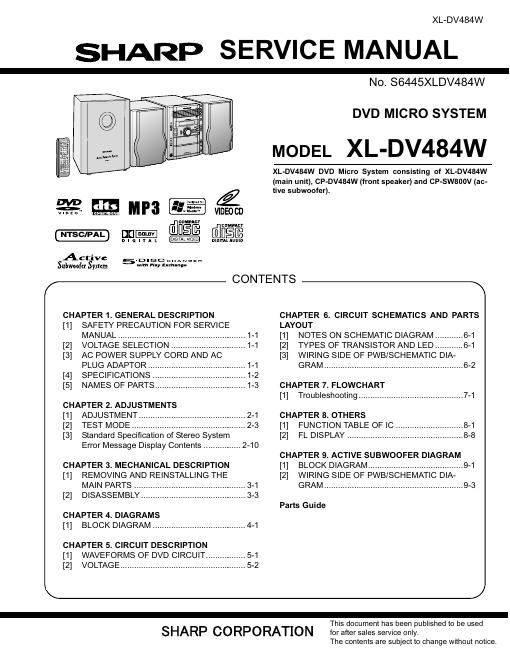
Sharp xl dv 484 w service manual

This is the 40 pages manual for sharp xl dv 484 w service manual.
Read or download the pdf for free. If you want to contribute, please mail your pdfs to info@audioservicemanuals.com.

Page: 1 / 40
left right
sharp xl dv 484 w service manual

Extracted text from sharp xl dv 484 w service manual (Ocr-read)


Page 1

V I!
LfiJiIEé
..DFI- MERE

XL- DV484W

SHARP SERVICE MANUAL

VIDEO CD

EDMMCY

A C the V D I s c :::::
Subwoofer System m" 1' mm"

/

CHAPTER 1. GENERAL DESCRIPTION

[1] SAFETY PRECAUTION FOR SERVICE
MANUAL ..........................

[2] VOLTAGE SELECTION

[3] AC POWER SUPPLY CORD AND AC

PLUG ADAPTOR .......
[4] SPECIFICATIONS .....
[5] NAMES OF PARTS ....................................... 1-3
CHAPTER 2. ADJUSTMENTS
[1] ADJUSTMENT .............................................. 2-1
[2] TEST MODE ................................................. 2-3
[3] Standard Specification of Stereo System

Error Message Disptay Contents ................ 2-10

CHAPTER 3. MECHANICAL DESCRIPTION
[1] REMOVING AND REINSTALLING THE

MAIN PARTS ................................................ 3-1
[2] DISASSEMBLY ............................................. 3-3
CHAPTER 4. DIAGRAMS
[1] BLOCK DIAGRAM .......... 4-1
CHAPTER 5. CIRCUIT DESCRIPTION
[1] WAVEFORMS OF DVD CIRCUIT ................. 5-1
[2] VOLTAGE ...................................................... 5-2

CONTENTS

N0. 86445XLDV484W

DVD MICRO SYSTEM

MODEL XL-DV484W

XL-DV484W DVD Micro System consisting of XL-DV484W
(main unit), CP-DV484W (front speaker) and CP-SWSOOV (ac-
tive subwoofer).

\

CHAPTER 6. CIRCUIT SCHEMATICS AND PARTS
LAYOUT

[1] NOTES ON SCHEMATIC DIAGRAM
[2] TYPES OF TRANSISTOR AND LED
[3] WIRING SIDE OF PWB/SCHEMATIC DIA-

GRAM ............................................................ 6-2
CHAPTER 7. FLOWCHART
[1] Troubleshooting ............................................. 7-1
CHAPTER 8. OTHERS
[1] FUNCTION TABLE OF IC ..... 8-1
[2] FL DISPLAY .............................. 8-8

CHAPTER 9. ACTIVE SUBWOOFER DIAGRAM

[1] BLOCK DIAGRAM ......................................... 9-1
[2] WIRING SIDE OF PWB/SCHEMATIC DIA-

GRAM ............................................................ 9-3
Parts Guide

/

This document has been published to be used

SHARP CORPORATION for after sales service only

The contents are subject to Change without notice.