Sharp qt 109 service manual

This is the 25 pages manual for sharp qt 109 service manual.
Read or download the pdf for free. If you want to contribute, please mail your pdfs to info@audioservicemanuals.com.

Page: 1 / 25
left right
sharp qt 109 service manual

Extracted text from sharp qt 109 service manual (Ocr-read)


Page 1

QT-270HIE/A
QT-109

SHARP

SERVICE MANUAL/SE3VlCE-ANLEITUNG/MANUEL DE SERVICE

m

PHOTO: QT-270H(BK)

- Note for users in UK
Recording and playback of any material may require consent which
SHARP is unable to give. Please refer particularly to the provisions
of CopyrightAct 1956, the Dramaticand Musical Performers Protection
Act 1956, the Performers Protection Acts 1963 and 1972 and to any
subsequent statutory enactments and orders

SO393QT270HBK

QT-270H(BK)
QT-27OE(BK)
QT-27OA(BK)

QT-109(BK)

- In the interests of user-safety the set should be restored to its original
condition and only parts identical to those specified be used.

- Im Interesse der Benutzer-Sicherheit some dieses Gerétt wieder auf
seinen ursprflnglichen Zustand eingestellt und nur die
vorgeschriebenen Teile verwendet warden,

- Dans Iinte'rét de la sécurité de Iutilisateur, Iappareil devra étre
reconstitué dans sa condition premiere et seules des pieces identiques
a celles spécifiees, doivent étre utilisées.

/-*- lNDEX TO CONTENTS b-fl
T?

k/

IMPORTANT SERVICE NOTES (FOR UK ONLY)
SPECIFICATIONS .................................................
NAMES OF PARTS
FITTING OF DIAL POINTER ..
DISASSEMBLY ......................
REMOVING AND FIEINSTALLING

THE MAIN PARTS ...............................
NOTES ON SCHEMATIC DIAGRAM


TYPES OF TRANSISTOR ..
ADJUSTMENT..
SCHEMATIC DIA
SIDE OF P.W.BOARD
EXPLODED VIEW .......
REPLACEMENT PARTS LIST .....
PACKING METHOD (FOR UK ON

® INHALTSVERZEICHNIS

TECHNISCHE DATEN
BEZEICHNUNG DER TEILE ..
ANBRINGEN DES SKALENZEIGERS .

ZERLEGEN .......................................
ENTFERNEN UND EINBAUEN DER
HAUPTTEILE ................................................................. 8,9

ANMERKUNGEN ZUM SCHEMATISCHEN

SCHALTPLAN ................................................... 10

TRANSISTOREN-TYPEN ..
EINSTELLUNG ...................
SCHEMATISCHER SCHALTPLAN/

VERDRAHTUNGSSEITE DER LEITERPLATTE ..... 15-48
EXPLOSIONSDARSTELLUNG .
ERSATZTEILLISTE ...................

® TABLE DES MATIERES

Page Page
CARACTERISTIQUES ..................................... 2,3 TYPES DE TRANSISTOR ....... 10
NOMENCLATURE ............... .4,5 REGLAGE ....................... 11-14
FIXATION DE LAIGUILLE .l .4,5 DIAGRAMME SCHEMATIQUE/COTE CABLAGE DE
DEMONTAGE ...................... LA PLAQUE'I'I'E DE MONTAGE IMPRIME 15~1a
DEMONTAGE ET REMONTAGE DES PIECES VUE EN ECLATE ..... .1920
PRINCIPALES .................................................. 8,9 LISTE DES PIECES D 21-23
REMARQUES CONCERNANT LE DIAGRAMME
SCHEMATIQUE ............................................................. 1o

SHARP CORPORATION

Page 2

QT-270H/E/A
QT-109

(9

TO THE OPERATION MANUAL.

FOR A COMPLETE DESCRIPTION OF THE OPERATION OF THIS UNIT, PLEASE REFER

IMPORTANT SERVICE NOTES (FOR UK ONLY)

Before returning the unit to the customer after completion of a
repair or adjustment it is necessary for the following withstand
voltage test to be applied to ensure the unit is safe torthe customer
to use.

WITHSTANDING
VOLTAG E TESTER

Setting of Withstanding Voltage Tester and set. Ac h 9%..

Set name set value D- our 3

withstanding Voltage Tester 6_ UNIT

Test voltage 4,240 VPEAK

3,000 VHMS i212)??? fifitiflLfififfaE

Set time 6 SECS SUPPLY CORD OF BATTERV TERMINAL

Set current(Cutotf current) 4 mA

Unit

Power/Function I Radio I FM mono

Judgment

0K: The GOOD" lamp lights.

NG: The NG" lamp lights and the buzzer sounds.

SPECIFICATIONS

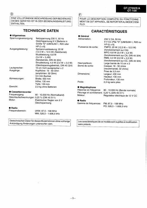
. General Speakers: 10 cm (4) full range speaker x 2
Power source: AC 230 V, 50 Hz Output terminal: Headphones; 16 -50 ohms
(QT-270H) DC 9 V ["D" size (UM/SUM - 1, R20 or (recommended; 32 ohms)

HP - 2) battery x 6]

Power source: AC 240 V, 50 Hz

(QT-270E) DC 9 V ["D" size (UM/SUM - 1, R20 or
HP - 2) battery x 6]

Power source: AC 220 - 240 V, 50 Hz

(QT-270N109) DC 9 V ["D" size (UM/SUM - 1, R20 or
HP - 2) battery x 6]

Output power: PMPO; 25 W (12.5 W + 12.5 W)

(QT-27OH) (AC operation)

MPO; 6.8 W (3.4 W + 3.4 W)
(AC operation, DIN 45 324)
RMS; 4.0 W (2.0 W + 2.0 W)
(DC operation, DIN 45 324)

Output power: MPO (Max); 7.6 W (3.8 W + 3.8 W)

(QT-270E) (AC operation)

HMS; 4.0 w (2.0 w + 2.0 W)

(DC operation, 10 % T.H.D.)
Output power: PMPO; 25 W (12.5 W + 12.5 W)
(QT-27OAH 09) (AC operation)

MPO (Max); 7.6 W (3.8 W + 3.8 W)

(AC operation)

RMS; 4.0 W (2.0 W + 2.0 W)
(DC operation, 1 kHz, 10 % T.H.D.)

Dimensions:

Weight:

0 Tape recorder
Frequency response:
Wow and flutter:
(QT-27OH)

Wow and flutter:
(QT-27OE/A/109)
Motor:

0 Radio
Frequency range:
(QT-270H/E)
Frequency range:
(QT-270A/ 1 09)

3.5 mm (1/8") socket

Width; 430 mm (16 - 15/16)
Height; 135 mm (5 < 3/8")

Depth; 130 mm (5 - 1/8")

2.3 kg (5.1 lbs.) without batteries

80 - 10,000 Hz (Normal tape)
0.25 % (DIN 45 511)

0.15 % (WRMS)

DC 9 V electric governor

FM; 87.5 - 108 MHz

AM; 526.5 -1,606.5 kHz

FM; 88 - 108 MHZ
AM: 526.5 ~1,606.5 kHz

notice.

Specifications forthis model are subject to change without prior