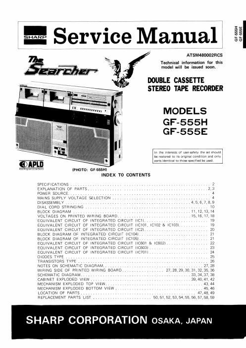
Sharp gf 555 e service manual

This is the 43 pages manual for sharp gf 555 e service manual.
Read or download the pdf for free. If you want to contribute, please mail your pdfs to info@audioservicemanuals.com.

Page: 1 / 43
left right
sharp gf 555 e service manual

Extracted text from sharp gf 555 e service manual (Ocr-read)


Page 1

= Seryice Manual

ATSM480002RCS

Technical information for this
model will be issued soon.

DOUBLE CASSETTE
STEREO TAPE RECORDER

MODELS

GF-555H
GF-555E

In the interests of user-safety the set should
be restored to its original condition and only
parts rdenticaI to those specified be used.

@APLD

Auto Program Lame Dame (PHOTO: G F 555)
INDEX TO CONTENTS

SPECIFICATIONS ......................................................... 2
EXPLANATION OF PARTS ................................................. 2,3
POWER SOURCE .......................................................... 4
MAINS SUPPLY VOLTAGE SELECTION ........................................ 4
DISASSEMBLY ................................................... 4,5,6,7,8,9
DIAL CORD STRINGING .................................................. IO
BLOCK DIAGRAM ................................................ 11,12,13,I4
VOLTAGES ON PRINTED WIRING BOARD .............................. I5, 16,17, 18
EQUIVALENT CIRCUIT OF INTEGRATED CIRCUIT IICII .......................... 19
EQUIVALENT CIRCUIT OF INTEGRATED CIRCUIT IICIOI, ICTO2 & ICIO3) ............ I9
EQUIVALENT CIRCUIT OF INTEGRATED CIRCUIT (IC2I .......................... 20
BLOCK DIAGRAM OF INTEGRATED CIRCUIT (ICIO4I ............................ 21
BLOCK DIAGRAM OF INTEGRATED CIRCUIT IICIOBI ............................ 21
EQUIVALENT CIRCUIT OF INTEGRATED CIRCUIT (IC601 & |C602) ................. 22
EQUIVALENT CIRCUIT OF INTEGRATED CIRCUIT IIC603I ........................ 23
EQUIVALENT CIRCUIT OF INTEGRATED CIRCUIT (IC7OII ........................ 24
DIODES TYPE .......................................................... 25
TRANSISTORS TYPE ..................................................... 26
NOTES ON SCHEMATIC DIAGRAM ......................................... 27,28
WIRING SIDE OF PRINTED WIRING BOARD. . . . . . . . . . . . . . . . , 27, 28,29,30,31,32,35, 36
SCHEMATIC DIAGRAM ............................................. 33,34,37, 38
CABINET EXPLODED VIEW ......................................... 39,40,4I,42
MECHANISM EXPLODED TOP VIEW ........................................ 43,44
MECHANISM EXPLODED BOTTOM VIEW .................................... 45,46
LOCATION OF PARTS ............................................... 47,48,49
REPLACEMENT PARTS LIST ........................ 50, 51,52, 53,54,55, 56, 57,58,593

SHARP CORPORATION OSAKA, JAPAN

GF555H

GF-555E