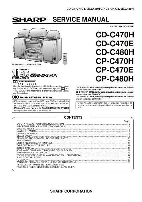
Sharp cp c 480 h service manual

This is the 98 pages manual for sharp cp c 480 h service manual.
Read or download the pdf for free. If you want to contribute, please mail your pdfs to info@audioservicemanuals.com.

Page: 1 / 98
left right
sharp cp c 480 h service manual

Extracted text from sharp cp c 480 h service manual (Ocr-read)


Page 1

CD-C470H,C470E,C480H/CP-C470H,C470E,C480H

SHARP

SERVICE MANUAL

Illustration: CD-CA70H/CP-C47DH

dues @mm

DIGITAL AUDIO

o_

p a o . L o a I c
Manufactured under license from Dolby Laboratories Licens-
ing Corporation. DOLBY, the double-D symbol DE] and
"PRO LOGIC" are trademarks of Dolby Laboratories Licens-
ing Corporation

C.) SOUND RETRIEVAL SYSTEM

- SR8 technology Licensed from SRS Labe. SFIS technology holds
the follwing patents: US. Patent No. 4,748,669, US. Patent No.
4,841,572 and US. Patent No. 4,866,774.

- SRS the SRS Logo (Q) and the SOUND RETRIEVAL SYSTEM
are registered trademarks of SRS Labs, Inc.

/__________________

SAFETY PRECAUTION FOR SERVICE MANUAL .....
IMPORTANT SERVICE NOTES (CD-C470E ONLY) ..
SPECIFICATIONS
NAMES OF PARTS ..
OPERATION MANUAL
DISASSEMBLY ............
REMOVING AND REINSTALLING THE MAIN PARTS
ADJUSTMENT .....................................
NOTES ON SCHEMATIC DIAGRAM ..
TYPE OF TRANSISTOR AND LED ..
BLOCK DIAGRAM ............................

FUNCTION TABLE OF IC ..
FL DISPLAY...
WIRING OF PR
REPLACEMENT PARTS LlST/EXPLODED VIEW

CONTENTS

SCHEMATIC DIAGRAM / WIRING SIDE OF P.W.BOARD
WAVEFORMS OF CD CIRCUIT .........................................
TROUBLESHOOTING (CD CHANGER CONTROL / CD SECTION)

PACKING OF METHOD (FOR CD-C47OE/CP-C47OE ONLY)

NO. $6738CDC470HE

CD-C47OH
CD-C470E
CD-C480H
CP-C470H
CP-C470E
CP-C480H

CD-CAI70H, CP-C470H, center speaker system and surround speaker
system constitute CD-CA7DH.
CD-C470E, cP-C470E, center speaker system and surround speaker
system constitute cn-c47oe.
CD-CASOH, CP-C480H, center speakersystem and surround speaker
system constitute CD-C480H.

- In the interests of user-safety the set should be restored to its
original condition and only parts identical to those specilied be
used.

SHARP CORPORATION

Page 2

CD-C470H,C470E,C480H/CP-C470H,C470E,C480H

SAFETY PRECAUTION FOR
SERVICE MANUAL

Precaution to be taken when replacing and servicing the
Laser Pickup.

The AEL (Accessible Emission Level) of Laser Power Output
forthis model isspecified to be lowerthan Class | Requirements.
However, the following precautions must be observed during
servicing to protect your eyes against exposure to the Laser
beam

(1) When the cabinet has been removed, the power is turned
on without a compact disc, and the Pickup is on a position
outerthan the lead-in position. the Laserwill lighttor several
seconds to detect a disc. Do not look into the Pickup Lens.

(2) The Laser Power Output of the Pickup inside the unit and
replacement service parts have already been adjusted prior
to shipping.

(3) No adjustment to the Laser Power should be attempted
when replacing or servicing the Pickup.

(4) Under no circumstances look directly into the Pickup Lens
at any time.

(5) CAUTION - Use of controls or adjustments, or performance
of procedures other than those specified herein may result
in hazardous radiation exposure.

Laser Diode Properties
Material: GaAlAs
Wavelength: 780 nm
Emission Duration: continuous
Laser Output: max. 0.6 mW

VAFIOITUS! LAITTEEN KAVTTAMINEN MUULLA KUINTAssA
KAYTTOOHJEESSA MAINITULLA TAVALLA SAATTAA
ALTISTAA KAYTTAJAN TURVALLISUUSLUOKAN 1
VLITTAVALLE NAKVMATTéMALLE LASERSATEILYLLE.

VAFlNlNG - 0M APPARATEN ANVANDs PAANNAT sATTAN I
DENNA BRUKSANVISNING SPECIFICERAS.
KANANVANDAREN UTsATTAs FéFt OSYNLIG
LASERSTRALNING, SOM OVERSKRIDER GHANSEN FOR
LASERKLASS 1.

(CD-C470H/ C D-C480H)

CLASS I LASER PRRDUET

APPAREIL A LASER llE CLASSE I
PRODUCT LASER DE CLASE I

LASER KLASSE l
LUOKAN l LASERLAITE
KLASS t LASEHAPPARAT
usznniiuw
LASERTRIEDY1

(CD-C470E)

CLASS I LASER PROIIUCT
APPAREIL A LASER DE CLASSE I
PRODUCT" LASER IIE ELASE I

IMPORTANT SERVICE NOTES (CD-C47OE ONLY)

Before returning the unit to the customer after completion of a
repair or adjustment it is necessary for the following withstand
voltage test to be applied to ensure the unit is safe for the
customer to use.

AC

WITHSTANDING
VOLTAG E TESTER

2? ®--(:

_ _ _ :I )- OUT
Setting of Withstanding Voltage Tester and set.
®--CD- N
Set name set value
. . . CONNECT THE PROBE
Withstanding Voltage Tester Egg/23w TO (END OF CHASSIS
Test voltage 4,240 VPEAK SUPP CORD SCREW
3.000 VFIMS IIISHIIIII IIIHIIIIIIII
Set time 6 secs UWWHW
flllflllflllilflflll
Set current(Cutoff current) 4 mA InnIIIIIIIIIII
Unit B IIIIEIIIIE
flflflllflflflt
Judgment fig 3%]
OK: The GOOD" lamp lights.
NG: The NG lamp lights and the buzzor sounds. '
CHASSIS
SCREW