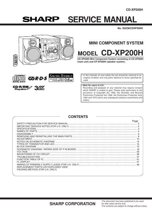
Sharp cd xp 200 h service manual

This is the 112 pages manual for sharp cd xp 200 h service manual.
Read or download the pdf for free. If you want to contribute, please mail your pdfs to info@audioservicemanuals.com.

Page: 1 / 112
left right
sharp cd xp 200 h service manual

Extracted text from sharp cd xp 200 h service manual (Ocr-read)


Page 1

CD-XP200H

SHARP SERVICE MANUAL

No. $5236CDXP200H

MINI COMPONENT SYSTEM

MODEL CD-XP200H

CD-XP200H Mini Component System consisting of CD-XPZOOH
(main unit) and CP-XPZODH (speaker system).

- In the interests at user-safety the set should be restored to its

comnncv
[fiILI§@ @R'D's STANDBY POWER 0 6W original condition and only parts identical to those specified be

N MPII N Sed_
DIGITAL AUDIO C0 SU O

GD-R/RW/ II/ - Note for users in U.K.

Recording and playback of any material may require consent
Playable DISC which SHARP is unable to give. Please reler particularly to the
provisions of Copyright Act 1956, the Dramatic and Musical
Performers Protection Act 1956, the Performers Protection Acts
1963 and 1972 and to any subsequent statutory enactments and
orders.

/- CONTENTS -\

SAFETY PRECAUTION FOR SERVICE MANUAL
IMPORTANT SERVICE NOTES (FOR U.K. ONLY) ..
SPECIFICATIONS .....
NAMES OF PARTS
DISASSEMBLY ..........
REMOVING AND REINSTALLING THE MAIN PARTS.
ADJUSTMENT ...............................................................
NOTES ON SCHEMATIC DIAGRAM
TYPES OF TRANSISTOR AND LED.
BLOCK DIAGRAM .............................
SCHEMATIC DIAGRAM / WIRING SIDE OF P.W.BOARD.
VOLTAGE ...................................
WAVEFORMS OF CD CIRCUIT.
TROUBLESHOOTING ..
FUNCTION TABLE OF I .
FL DISPLAY ......................
WIRING OF PRIMARILY SUPPLY LEADS (FOR U.K. ONLY) ..
REPLACEMENT PARTS LIST/EXPLODED VIEW

PACKING METHOD (FOR U.K. ONLY)


-
This document has been published to be used

SHARP CORPORATION for after sales service only.

The contents are subject to change without notice.

Page 2

CD-XP200H

SAFETY PRECAUTION FOR SERVICE MANUAL

Precaution to be taken when replacing and servicing the
Laser Pickup.

The AEL (Accessible Emission Level) of Laser Power Output
for this model is specified to be lower than Class 1
Requirements. However, the following precautions must be
observed during servicing to protect youreyes against exposure
to the Laser beam.

(1) When the cabinet has been removed, the power is turned
on without a compact disc, and the Pickup is on a position
outerthan the lead-in position, the Laserwill light forseveral
seconds to detect a disc. Do not look into the Pickup Lens.

(2) The Laser Power Output of the Pickup inside the unit and
replacement service parts have already been adjusted prior
to shipping.

(3) No adjustment to the Laser Power should be attempted
when replacing or servicing the Pickup.

(4) Under no circumstances look directly into the Pickup Lens
at any time.

(5) CAUTION - Use of controls or adjustments, or performance
of procedures other than those specified herein may result
in hazardous radiation exposure.

Laser Diode Properties
Material: GaAIAs
Wavelength: 780 nm
Emission Duration: continuous
Laser Output: max. 0.6 mW

um mmlnu wueu um

Elll'llnlt-IIWISIILE
an an aunt tum BUM an Vliw mnzmv wmi

iii-rim mnrunzm

lellllllli IllslcllfllllE imnxrxmtm vim Emir
sEnrrIEr mun lit at: mmuis SEHIIIEI um
nmm mr nmxcuzu mirsumztu Izrnwril.
AHEIIlnI ilAVlII lAsEn minim Ell m llmlllEFiItlFtE.
HE Ms llEitlllllEll tE mum mnmfllm nu AVE! nu
insinunzm nHlDIIEs

ADVERSELVSVNLIG 0G USYNLlG LASERSTRALING VED ABNING. SE IKKE lND l
STRALENVHELLER IKKE MED OPTlSKE INSTRUMENTER.

VAROt AVATTAESSA OLET ALTTllNA NAkaALLE JA NAKVMAHOMALLE
LASERSATEILYLLE ALA TUlJOTA SATEESEEN ALAKA KATSO SITA OPTISEN
LAITTEEN LAPI.

VARNINGVSYNLIG OCH OSYNLIG LASERSTRALNING MAR DENNA DEL AH
OPPNAD. STIRRA EJ IN I STRALEN OCH BETRAKTA EJ STRALEN GENOM
OPTISKT lNSTFtUMENT.

Winonusr LAITI'EEN KAVTTAMINEN MUULLA KUIN TAssA
KevnooHJEESSA MAINITULLA TAVALuLA' SAATTAAHALTISHTAA
KAVTrAgAN TUHVALLISUUSLUOKAN 1 VLITIAVALLE NAKVMATrOMALLE
LASEHSATEILVLLE.

VAHNING » OM APPARATEN ANVANDS PA ANNAT SATT AM I DENNA
BRUKSANVISNING SPECIFICERAS. KAN ANVANDAHEN UTsIu'rAs Fort
OSYNLIG LASERSTHALNING, $0M DVEHSKRIDEH GHANSEN Fort
LASERKLASS 1.

IMPORTANT SERVICE NOTES (FOR U.K. ONLY)

Before returning the unit to the customer after completion of a
repair or adjustment it is necessary for the following withstand
voltage test to be applied to ensure the unit is safe for the
customer to use.

Setting of Withstanding Voltage Tester and set.

Set name set value

Withstanding Voltage Tester

Test Voltage 4,240 VPEAK
3,000 VRMS

Set time 6 secs

Set current (Cutoff current) 4 mA

Unit

Judgment

OK: The GOOD" lamp lights.
NG: The NG lamp lights and the buzzer sounds.

WITHSTANDING

VOLTAGE TESTER PROBE

-1

AC

@-

e-( )- UNIT
SHORT-CIRCUIT
AC POWER
SUPPLY CORD

CONNECT THE PROBE
TO GND OF CHASSIS
SCREW