Sharp cd sw 340 h service manual

This is the 152 pages manual for sharp cd sw 340 h service manual.
Read or download the pdf for free. If you want to contribute, please mail your pdfs to info@audioservicemanuals.com.

Page: 1 / 152
left right
sharp cd sw 340 h service manual

Extracted text from sharp cd sw 340 h service manual (Ocr-read)


Page 1

CD-SW34OH

SERVICE MANUAL

N0. S5824CDSW34OH

MINI COMPONENT SYSTEM

MODEL CD-SW340H

[ For Europe, U.K., Australia and New Zealand ]

CD-SW340H Mini Component System consisting of
CD-SW34OH (main unit), CP-$340H (front speaker)
and CP-SW340H (subwoofer).

- In the interests of user-safety the set should be restored
to its original condition and only parts identical to those
specified be used.

COMPACT _ Mays
dInS® mwflh :. Windows

- Note for users in U.K.

mm-um NAVIGATHIN TM MEdiaw Recording and playback of any material may require
consent which SHARP is unable to give. Please refer
@R'D'S ENE SAVING ENERGY particularly to the provisions of Copyright Act 1956, the
S'AFLIR'EWEIJE 0.6w Performers Protection Acts 1963 and 1972 and
CD R/RW subsequent statutory enactments and orders.
playabie/ 5'91512
CONTENTS \

PRECAUTIONS FOR USING LEAD-FREE SOLDER
CHAPTER 1. GENERAL DESCRIPTION

[1] Safety Precaution For Service Manual .......... 1-1
[2] Important Service Notes (for U.K. only) . 1-2
[3] Specifications ................................................ 1-2
[4] Name Of Parts .............................................. 1-4
CHAPTER 2. ADJUSTMENTS

[1] Mechanism Section ....................................... 2-1
[2] Test Mode ...... 2-2

[3] CD Section.... 2-4

CHAPTER 3. MECHANISM BLOCKS
[1] Caution On Disassembly ............................... 3-1
[2] Removing And Reinstalling The Main Parts ..... 3-4

CHAPTER 4. DIAGRAMS
[1] Main Block Diagrams .....
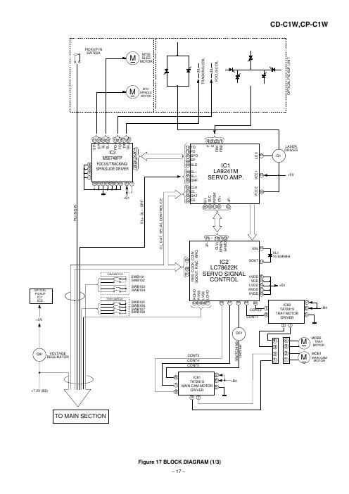
[2] CD Block Diagrams ........

k

....4-1
...4-3

CHAPTER 5. CIRCUIT DESCRIPTION
[1] Waveforms Of CD Circuit ......
[2] Voltage ...................................


CHAPTER 6. CIRCUIT SCHEMATICS AND PARTS
LAYOUT

[1] Notes On Schematic Diagram ......
[2] Types Of Transistor And LED

e2

[3] Schematic Diagram ..................

[4] Charts Of Connecting Wires .......... 6-24
[5] Wiring Side Of PWB ...................... 6-26
CHAPTER 7. FLOWCHART

[1] Troubleshooting ............................................. 7»1

CHAPTER 8. OTHERS
[1] Function Table Of IC....
[2] FL Display ....................

PARTS GUIDE

Parts marked with HA are important for maintaining the safety of the set. Be sure to replace these parts with
specified ones for maintaining the safety and performance of the set.

SHARP CORPORATION

This document has been published to be used
for after sales service only.
The contents are subject to change without notice.

Page 2

CD-SW340H
PRECAUTIONS FOR USING LEAD-FREE SOLDER

1. Employing lead-free solder

"MAIN, POWER, DISPLAY, AUDIO IN, CD, FRONT SPEAKER LED, SUBWOOFER LED PWB" of this model
employs |ead~free solder. The LF symbol indicates lead-free solder, and is attached on the PWB and service
manuals. The alphabetical character following LF shows the type of lead-free solder.

Example: BE a

sn-Ag-CU Indicates lead-free solder of tin, silver and copper,

2. Using lead-free wire solder
When fixing the PWB soldered with the lead-free solder, apply lead-free wire solder. Repairing with conventional
lead wire solder may cause damage or accident due to cracks.
As the melting point of |ead~free solder (Sn-Ag-Cu) is higher than the lead wire solder by 40 C, we recommend
you to use a dedicated soldering bit, if you are not familiar with how to obtain lead-free wire solder or soldering
bit, contact our service station or service branch in your area.

3. Soldering

As the melting point of lead-free solder (Sn~Ag-Cu) is about 220°C which is higher than the conventional lead
solder by 40°C,and as it has poor solder wet ability, you may be apt to keep the soldering bit in contact with the
PWB for extended period of time. However, since the land may be peeled of for the maximum heat-resistance
temperature of parts may be exceeded, remove the bit from the PWB as soon as you confirm the steady
soldering condition.

Lead-free solder contains more tin, and the end of the soldering bit may be easily corrected. Make sure to turn
on and off the power of the bit as required. If a different type of solder stays on the tip of the soldering bit, it is
alloyed with |ead~free solder. Clean the bit after every use of it.

When the tip of the soldering bit is blackened during use, file it with steel wool or fine sand paper.

Be careful when replacing parts with polarity indication on the PWB silk.

Lead-free wire solder for servicing

Ref No. Parts No. Description
PWB-A 92LPWB7285MANS MAIN (A1), POWER (A2)

PWB-B 92LPWB7285DPLS DISPLAY (Bl), AUDIO IN (BZ)

PWB-C 92LPWB7285CDUS CD

PWB-D 92LPWB6514LEDS FRONT SPEAKER LED

PWB-E 92LPWB7285LEDS SUB WOOFER LED