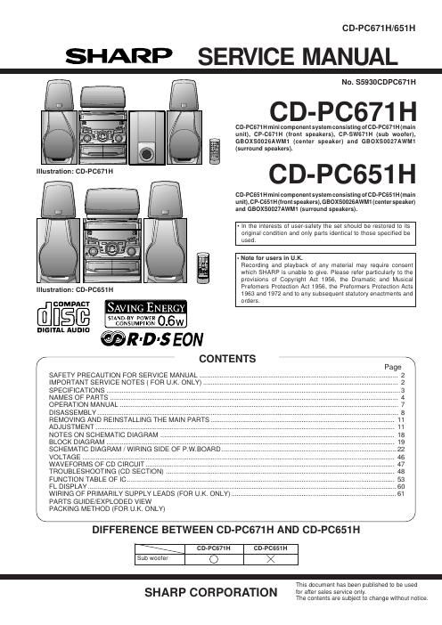
Sharp cd pc 651 h service manual

This is the 80 pages manual for sharp cd pc 651 h service manual.
Read or download the pdf for free. If you want to contribute, please mail your pdfs to info@audioservicemanuals.com.

Page: 1 / 80
left right
sharp cd pc 651 h service manual

Extracted text from sharp cd pc 651 h service manual (Ocr-read)


Page 1

CD-PC671H/651H

SHARP SERVICE MANUAL

N0. $5930CDPCG71 H

CD-PC671 H

CD-PC671 H mini component system consisting och-PC671 H (main
unit), CP-CG71H (front speakers), CP-SWG71H (sub woofer),
GBOXSOO26AWM1 (center speaker) and GBOX50027AWM1
(surround speakers).

CD-PC651 H

CD-PCGSt H mini component system consisting ofCD-PC651 H (main
unit), CP-CB51 H (front speakers), GBOXSOOZBAWMt (center speaker)
and GBOXSODZ7AWM1 (surround speakers).

- In the interests of user-safety the set should be restored to its
original condition and only parts identical to those specified be
used.

- Note for users in U.K.
Recording and playback of any material may require consent
which SHARP is unable to give. Please refer particularly to the
provisions of Copyright Act 1956, the Dramatic and Musical
Prefomers Protection Act 1956, the Preformers Protection Acts
1963 and 1972 and to any subsequent statutory enactments and

[filmmm SAVING ENERGY r
@R-D'SEON

/- CONTENTS %

SAFETY PRECAUTION FOR SERVICE MANUAL .....
IMPORTANT SERVICE NOTES ( FOR UK. ONLY)
SPECIFICATIONS ..
NAMES OF PARTS
OPERATION MANUAL ..
DISASSEMBLY ..........
REMOVING AND REINSTALLING THE MAIN PARTS
ADJUSTMENT ...................................
NOTES ON SCHEMATIC DIAGRAM
BLOCK DIAGRAM .............................
SCHEMATIC DIAGRAM / WIRING SIDE OF P.W.BOARD
VOLTAGE ..
WAVEFORM .
TROUBLESHOOTING (CD SECTION)
FUNCTION TABLE OF IC.
FL DISPLAY ......................

Illustration: CD-PC651H

WIRING OF PRIMARILY SUPPLY LEADS (FOR U.K. ONLY). "61
PARTS GUIDE/EXPLODED VIEW
PACKING METHOD (FOR U.K. ONLY)
\ /
DIFFERENCE BETWEEN CD-PC671 H AND CD-PC651 H
CD-PC671H CD-PC651H
Sub woofer O X

-
This document has been published to be used

SHARP CORPORATION lor alter sales service only.

The contents are subject to change without notice.

Page 2

CD-P0671H/PC651H

SAFETY PRECAUTION FOR
SERVICE MANUAL

Precaution to be taken when replacing and servicing the
Laser Pickup.

The AEL (Accessible Emission Level) of Laser Power Output
forthis model is specified to be lowerthan Class | Requirements.
However, the following precautions must be observed during
servicing to protect your eyes against exposure to the Laser
beam.

(1) When the cabinet has been removed, the power is turned
on without a compact disc, and the Pickup is on a position
outerthan the lead-in position, the Laserwill light forseveral
seconds to detect a disc. Do not look into the Pickup Lens.

(2) The Laser Power Output of the Pickup inside the unit and
replacement service parts have already been adjusted prior
to shipping.

(3) No adjustment to the Laser Power should be attempted
when replacing or servicing the Pickup.

(4) Under no circumstances look directly into the Pickup Lens
at any time.

(5) CAUTION - Use of controls or adjustments, or performance
of procedures other than those specified herein may result
in hazardous radiation exposure.

(Except for U.K.)
llllllllllllllllllll llllllllllllllllllll

llllllllllllllllllll llllllllllllllllllll
I llllllllllllllllllll

iii um

I m iiiii]i.ne{
Uiiug. t -.
or] lit] Ill]
[Jillllltit] [00
iii lLlL

a {as

L _

ELISE I LASER PRODUCT

APPAREIL R LASER IIE ELASSE I
PRIIIJUCTI'I LASER IIE LLASE I

LASER KLASSE i
LUOKAN 1 LASERLAlTE
KLASS 1 LASERAPPARAT
LASER TRiov 1
lASERTRIEDV1

(For U.K.)

llllllllllllllllllll llllllllllllllllllll

llllllllllllllllllll I

m] urn Efltfllflf H
uranJLu[[_., 0k

cuss l LASER PRODUCT DEDJHJED

APPAREIL ii LASER DE ELASSE l C] IJJIJJEIJtIJJIJDEIJ

Pnunucra LASER llE CLASE l HJHJEDEWD @J

[llfl IIJIJE

Laser Diode Properties
Material: GaAlAs
Wavelength: 780 nm
Emission Duration: continuous
Laser Output: max. 0.6 mW

CAUTIONLNVISIBLE LASER RADIATION WHEN OPEN [)0 NOT STARE INTO
mm OR VIEW mar-mu WITH 0mm mmL'MEMs
VARNINGQS\MJG LASERSTRALNING NAR DENNA DEL AR OPPNAD STIRRA
E] IN | STRALEN OCH BETRAKTA Ll S'TRALEN MED OPTISKA INSTRUMENT
Anvpmuusymc Hummus vLo ABMM. s: "(Kn IND |
STRALENVILELLBI IKKE MED OPHSKE INSTRIJMLATER

VARU AVATI'ALSSA ULEI' ALTI'IINA NAKYMATON LASERSATEILYLLE
ALA TL'IJUTA SATIISIEEN ALAKA KATSO SITA OPTISEN LAI'I'TEEN LAPI
VARNINGrOSYN'IJG LASERSTRALNI'NG NAR DENNA DEL AR OPPKAD
STIRRA LIIN | STRALEN OCH BETRAKTA EJ STRALEN GENOM OPTISKT
INSTRUMENT

ADVERSEIfUSYNLIG LASERSTRALING NAR DEKSEL AYN'ES STIRRIKKE

NN I STRALEN ELLE? SE DIREKTE MED OPTISKE INSTRL'MEkTER

vARoITus! LAITTEEN KeVTTéMINEN MUULLA KUlN
TéSSé

KéVTTiS oHJEESsA MAINITULLA TAVALLA SAATIAA
ALTISTAA KeVTTéJéN TURVALLISUUSLUOKAN 1
VLlTre'VéLLE NeKVMeTTéMeLLE LASERSeTEILVLLE.

VARNING - OM APPARATEN ANVeNDs Pe ANNAT sél'r
éN I DENNA ERUKSANVISNING SPECIFICERAS. KAN
ANVé NDAREN UTSé TTAS F6 R OSVNLIG
LASERSTRéLNING. 50M fiVERSKRlDER GRéNSEN FéR
LASERKLASS t.

IMPORTANT SERVICE NOTES (FOR U.K. ONLY)

Before returning the unit to the customer after completion of a
repair or adjustment it is necessary for the following withstand
voltage test to be applied to ensure the unit is safe for the
customer to use.

Setting of Withstanding Voltage Tester and set.

Set name set value

Withstanding Voltage Tester

Test voltage 4,240 VPEAK
3,000 VRMS

Set time 6 secs

Set current(Cutofl current) 4 mA

Unit

Judgment

OK: The GOOD" lamp lights.
NG: The NG lamp lights and the buzzor sounds.

WlTHSTANDlNG
VOLTAGE TESTER

9-:-
AC
Di 2? our
®_-CD7 UNIT

SHORTrClRCUIT CONNECT THE PROBE
AC POWER TO END OF CHASSlS
SUPPLY CORD SCREW