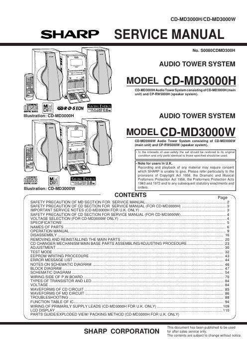
Sharp cd md 3000 h service manual

This is the 132 pages manual for sharp cd md 3000 h service manual.
Read or download the pdf for free. If you want to contribute, please mail your pdfs to info@audioservicemanuals.com.

Page: 1 / 132
left right
sharp cd md 3000 h service manual

Extracted text from sharp cd md 3000 h service manual (Ocr-read)


Page 1

CD-MD3000H/CD-MD3000W

SHARP SERVICE MANUAL

No. SOOBOCDMDSOOH

AUDIO TOWER SYSTEM

MODEL CD-MD3000H

CD-MDSOOOH Audio Tower System consisting of CD-MDSUODH (main
unit) and CP-RW5000H (speaker system).


WWI SAVING ENERGY

mm. mm
nlsluL nunlo ( tmwwwm 0.6w

Illustration: CD-MD3000H AUDIO TOWER SYSTEM

MODEL CD-MD3000W

CD-MDSOOOW Audio Tower System consisting of CD-MDSODOW
(main unit) and CP-FIW5000W (speaker system).

- In the interests 01 userrsalety the set should be restored to its original
condition and only parts identical to those specilied should be used.

- Note Ior users in U.K.
Recording and playback of any material may require consent
which SHARP is unable to give. Please refer particularly to the
provisions of Copyright Act 1956, the Dramatic and Musical

cum-um

SAVING ENERGY Prefomers Protection Act 1956, the Preformers Protection Acts
mainlmnm SISgtEIJfiIEI 0.8w 1963 and 1972 and to any subsequent statutory enactments and
Illustration: CD-Moaooow orders
/- CONTENTS -Page\
SAFETY PRECAUTION OF MD SECTION FOR SERVICE MANUAL .................................... .2
SAFETY PRECAUTION OF CD SECTION FOR SERVICE MANUAL (FOR CD»MD3000H) . .3
IMPORTANT SERVICE NOTES (CD-MD3000H FOR UK. ONLY) ..................................... 3
SAFETY PRECAUTION OF CD SECTION FOR SERVICE MANUAL (FOR CD-MD3000W) .. .4
VOLTAGE SELECTION (FOR CD-MD3000W ONLY) .. .4
SPECIFICATIONS ......................................................... 5
NAMES OF PARTS ....... .. 6
OPERATION MANUAL .. 9
DISASSEMBLY .............. . 16
REMOVING AND REINSTALLING THE MAIN PARTS. . 20
CD CHANGER MECHANISM MAIN BASE PARTS ASSEMBLING/ADJUSTING PROCEDURE . 23
ADJUSTMENT. . 30
TEST MODE . 32
EEPROM WRIT . 43
ERROR MESSAGE LIST ................ . 44
NOTES ON SCHEMATIC DIAGRAM . . 46
BLOCK DIAGRAM ............ . 47
SCHEMATIC DIAGRAM . 54
WIRING SIDE OF P,W.BOARD.. . 70
TYPES OF TRANSISTOR AND L . 84
VOLTAGE .................................... . 84
WAVEFORMS OF CD CIRCUIT. . 85
WAVEFORMS OF MD CIRCUIT. . 86
TROUBLESHOOTING ...... . 88
FUNCTION TABLE OF IC.
WIRING OF PRIMARILY SUPPLY LEADS (CD-MD3000H FOR U.K. ONLY).
LCD DISPLAY ...................................................................................................

\ PARTS GUIDE/EXPLODED VIEW/ PACKING METHOD (CD»MD3000H FOR U.K. ONLY) /

-
This document has been published to be used

SHARP CORPORATION for after sales service only.

The contents are subject to change without notice.

Page 2

CD-MD3000H/CD-MD3000W
SAFETY PRECAUTION OF MD SECTION FOR SERVICE MANUAL

WARNINGS
The AEL (ACCESSIBLE EMISSION LEVEL) of the laser power output is less than class 1 but the laser component is capable of emitting
radiation exceeding the limit for class 1. Therefore it is important that the following precautions are observer during servicing to protect your
eyes against exposure to the laser beam.
1 ) When the unit case cover is removed and LOADING SW (SW 1956) is turned on and then PLAY SW (SW 1954 mechanism PWB) is turned
on in a lew second.
The laser will light for several second to detect a disk.
2) The laser power output of the pickup unit and replacement service parts are all factory pre-set before shipment.
Do not attempt to re-adjust the laser pickup unit during replacement or servicing.
3) Under no circumstances stare into the pickup lens at any time.
4) If laser optical unit becomes faulty, replace the complete laser optical unit.
5) CAUTION-USE of controls or adjustments, or performance of procedures other than those specified herein may result in hazardous
radiation exposure.

CAUTIONVINVISLELE LASER RADIATION WHEV OPEN AND INTERMXJKS DEFEATED
AVOID EXPOSURE TO BEAM

VARNINGVOSVN'LIG LASERSTR LI\L\l(i NR DENNA DEL R WNAD 0m SPRRAR
R LI'RKOPPLADE sTRLEN R FARIJG

ADVARSELVUSYNLIG LASERSTRLING NR DEKSEL PNEs (x1 lekERHEDsLs
BerEs UNNU EKsmNERING FOR STR LEN

VARO AVATI'AESSA JA SUUJALUKITUS ()HITETI'AESSA OLEI' ALTTIINA
NKYMT N LASERSTEILYLLE L KATSO sTEEsEN

VARNINGJXSYHUG LASERSTR LING NR DENNA DEL R PPNAD (XJH SPRREN
R URKUPPLAD BEI'RAKTA El STRLFN

ADVARSELVUSYNLIG LASERSTR LING VED BMNG N R SlKKERHEDfiAI-BRYDERE
ER UDE AI- FUNKTION UNDG UDSETI'ELSE FUR s'rRLLNo

VAROITUS! LAITI'EEN KAYTTAMINEN MUULLA KU_IN rAssA KAYTTOOHJEESSA MAI
Laser Diode Properties NITULLA TAVALLA SAA'I'I'AA ALTISTAA KAVTTAJAN TURVALLISUUSLUOKAN 1

. vurrlivALLE NAKVMATTOMALLE LASERSATEILYLLE.
0 Material: GaAIAs ._ .. ..
W | h' VARNING - OM APPARATEN ANVANDS PA ANNAT SATT AN I DENNA BRUKSANVISNI
. 3V8 engt - 785 nm NG SPECIFICERAS. KAN ANVANDAfiEN UTSATI'AS FOR OSYNLIG LASERSTRALNING,
. Pulse time: SOM OVERSKRIDER GRANSEN FOR LASERKLASS 1.

Read mode: 0.8 mW Continuous

Write mode: max 10 mW 0.58
min cycle 1.58
Repetition

VARO l Avattaessa ja suojalukitus ohitettaessa olet alttiina nakymattomalle lasersateilylle. Ala katso sateeseen.
VARNING! Osynlig laserstralning nar denna del ar oppnad och sparren ar urkopplad. Betrakta ej stralent

Precaution to be taken when replacing and servicing the laser pickup.

The following precautions must be observed during servicing to protect your eyesvagainst exposure to the laser.

Warning of possible eye damage when repairing:

Ifthe AC power plug is connected when the inner cover of the unit is removed, the laser will light up during focus access (about
1 second) (Fig. 2-1).

During this operation, the laser will leak from the opening between the magnetic head and cartridge holder (Fig. 22).

In order to protect your eyes, you must not look at the laser during repair.

Before repairing, be sure to disconnect the AC power plug.

Magnetic Head
/- Laser Beam
m Cartridge Holder

Mechanism
Chassis

Spindle Motor Optical Pickup

Figure 2-1 Figure 2-2