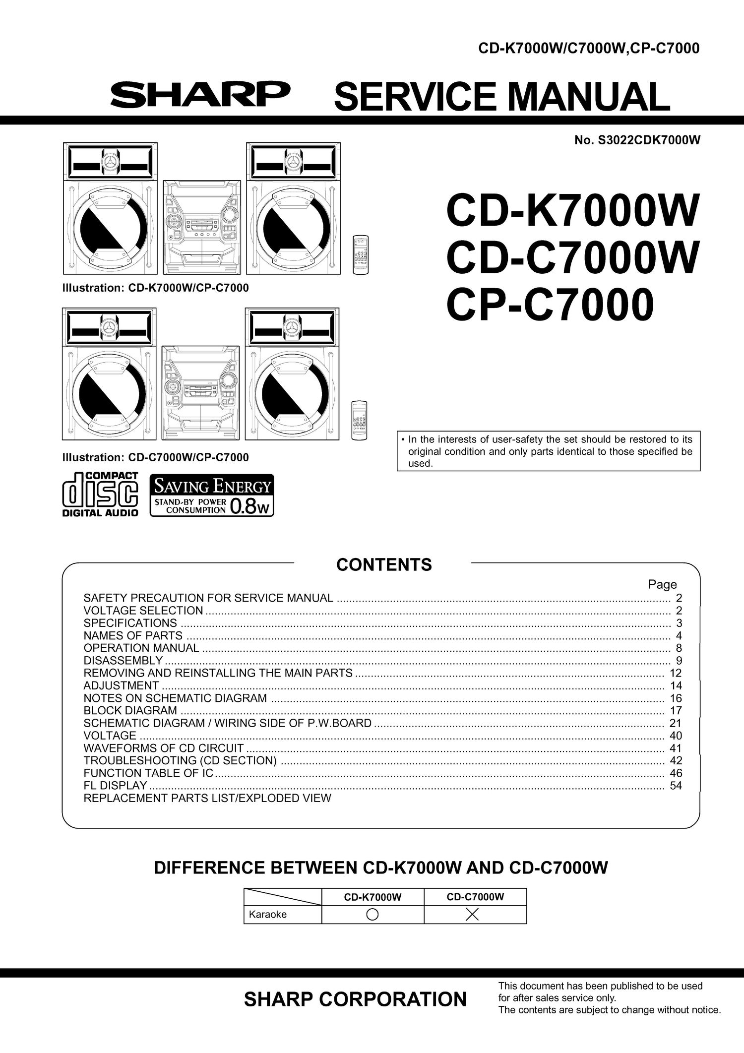
Sharp cd k 7000 w service manual

This is the 19 pages manual for sharp cd k 7000 w service manual.
Read or download the pdf for free. If you want to contribute, please mail your pdfs to info@audioservicemanuals.com.

Page: 1 / 19
left right
sharp cd k 7000 w service manual

Extracted text from sharp cd k 7000 w service manual (Ocr-read)


Page 2

CD-K7000W/C7000W,CP-C7000

NOTES ON SCHEMATIC DIAGRAM

. Resistor:
To differentiate the units of resistors, such symbol as K and
M are used: the symbol K means 1000 ohm and the symbol
M means 1000 kohm and the resistor without any symbol is
ohm-type resistor. Besides, the one with Fusible is a fuse

To indicate the unit of capacitor, a symbol P is used: this
symbol P means micro-micro-farad and the unit of the
capacitor without such a symbol is microfarad. As to
electrolytic capacitor, the expression capacitance/withstand
voltage is used.
(CH), (TH), (RH), (UJ): Temperature compensation
(ML): Mylar type
(P.P.): Polypropylene type

. Schematic diagram and Wiring Side of P.W.Board for this
model are subject to change for improvement without prior
noflce.

SW4

PICKUP IN ON-fi
SW701 ON/STAD-BY
SW702 CLOCK
SW703 TIMER/SLEEP
SW709 DISC 1 ON-fl
8ku
SW712 DISC SKIP ON- FF
SW713 OPEN/CLOSE
SW714 DIMMER
SW715 X-BASS/MEMO
SW716 EQUALIZER
SW717 SURROUND
SW718 REV MODE
SW719 CD
SW723 TAPE

O
IZ
O
n
'n

O
I2
O
TI
TI

O
IZ
|O
TI
TI

0

O
IZ
O
'n
'n

O
IZ
0
'fi
TFI

O
IZ
0
TI
'n

O
IZ
O
TI
TI

O
IZ
O
TI
'n

O
IZ
|O
'n
'n

O
IZ
O
TI
TI

O
IZ
O
TI
TI

FRONT
VIEW

E c B

(S) (G) (D)

(1) (2) (3)
2SA1015 GR KTC2026
2SC1845 F KTC3203 Y
2SC3203 Y KTC3194 Y
28K246 GR KTC3199 GR
KTA1266 GR KRA107 M
KTA1271 Y KRC102 M
KTA1273 Y KRC104 M
KTA1274 Y KRC1 07 M

. The indicated voltage in each section is the one measured
by Digital Multimeter between such a section and the chas-
sis with no signal given.
1.|nthetunersecflon,

( ) indicates AM
< > indicates FM stereo
2. In the main section, a tape is being played back.
3. In the deck section, a tape is being played back.
( ) indicates the record state.
4. In the power section, a tape is being played back.
5. In the CD section, the CD is stopped.

. Parts marked with A ( I: I Z I :l) are important for
maintaining the safety of the set. Be sure to replace these
parts with specified ones for maintaining the safety and
performance of the set.

REF. NO DESCRIPTION POSITION

SW724 TUNING DOWN
SW725 MEMORY/SET

SW726 TRACK DOWN/REVIEW/
PRESET DOWN/REWIND

FAST FORWARD

swm
swvso
swm
swm
swm

SW734 TUNER (BAND)
sws01

SW727

SW728

VOLTAGE SELECTOR

230-240-220
-127-1 10

SWM1 T1 PLAY ON-OFF
SWM2 T2 PLAY ON-OFF
SWM3 F.PLAY ON-OFF

SWM4 R.PLAY ON-OFF

FRONT
VIEW


->F'
4204SRT7

4204UGT7
4204 UYT7

Figure 16 TYPES OF TRANSISTOR AND LED

-16-