Sharp cd ea 135v

This is the 48 pages manual for sharp cd ea 135v.
Read or download the pdf for free. If you want to contribute, please mail your pdfs to info@audioservicemanuals.com.

Page: 1 / 48
left right
sharp cd ea 135v

Extracted text from sharp cd ea 135v (Ocr-read)


Page 1

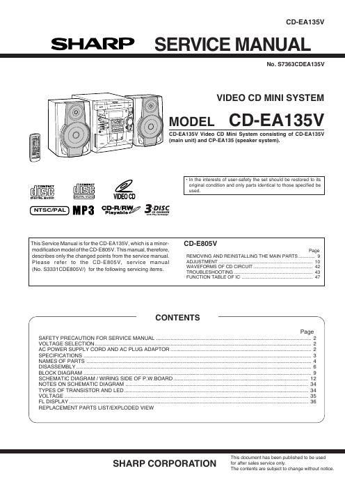
CD-EA135V

SHARP SERVICE MANUAL

N0. S7363CDEA135V

VIDEO CD MINI SYSTEM

MODEL CD-EA135V

CD-EA135V Video CD Mini System consisting of CD-EA135V
(main unit) and CP-EA135 (speaker system).

- In the interests of user-safety the set should be restored to its
@cumpncr @figé é original condition and only parts identical to those specified be
used.
nlnltflléfi VIDEO CD
CD-H/RW -DISC
NTSC/PAL M P3 playahie/ 3 n
This Service Manual is forthe CD-EA135V, which is a minor- CD-E805V
modification model ofthe CD-EBOSV. This manual, therefore,
describes only the changed points from the service manual. REMOVING AND REINSTALLING THE MAIN PARTS
Please refer to the CD-E805V, service manual ADJUSTMENT ------------------------
(No. 83331CDE805VI) for the following servicing items. WAVEFORMS 0F CD C'RCU' -

TROUBLESHOOTING .....
FUNCTION TABLE OF IC

CONTENTS

SAFETY PRECAUTION FOR SERVICE MANUAL ..
VOLTAGE SELECTION ........................................
AC POWER SUPPLY CORD AND AC PLUG ADAPTOR ..
SPECIFICATIONS .....
NAMES OF PARTS
DISASSEMBLY
BLOCK DIAGRA ..
SCHEMATIC DIAGRAM / WIRING SIDE OF P.W.BOARD
NOTES ON SCHEMATIC DIAGRAM
TYPES OF TRANSISTOR AND LED
VOLTAGE ..
FL DISPLAY ..
REPLACEMENT PARTS LIST/EXPLODED VIEW

-
This document has been published to be used

SHARP CORPORATION for after sales service only.

The contents are subject to change without notice.

Page 2

CD-EA135V
SAFETY PRECAUTION FOR SERVICE MANUAL

WARNINGS
THE AEL (ACCESSIBLE EMISSION LEVEL) OF THE LASER POWER OUTPUT IS LESS THAN CLASS 1 BUT THE LASER
COMPONENT IS CAPABLE OF EMITTING RADIATION EXCEEDING THE LIMIT FOR CLASS 1. THEREFORE IT IS
IMPORTANTTHAT THE FOLLOWING PRECAUTIONS ARE OBSERVED DURING SERVICING TO PROTECT YOUR EYES
AGAINST EXPOSURE TO THE LASER BEAM.
1-WHEN THE CABINET IS REMOVED, THE POWER IS TURNED ON WITHOUTA COMPACT DISC IN POSITION ANDTHE
PICKUP IS ON THE OUTER EDGE THE LASER WILL LIGHT FOR SEVERAL SECONDS TO DETECT A DISC. DO NOT
LOOK INTO THE PICKUP LENS.
2-THE LASER POWER OUTPUT OF THE PICKUP UNIT AND REPLACEMENT SERVICE PARTS ARE ALL FACTORY
PRESET BEFORE SHIPMENT.
DO NOT ATTEMPT TO READJUST THE LASER PICKUP UNIT DURING REPLACEMENT OR SERVICING.
3-UNDER NO CIRCUMSTANCES STARE INTO THE PICKUP LENS AT ANY TIME.
4-CAUTION-USE OF CONTROLS OR ADJUSTMENTS, OR PERFORMANCE OF PROCEDURES OTHER THAN THOSE
SPECIFIED HEREIN MAY RESULT IN HAZARDOUS RADIATION EXPOSURE.

Laser Diode Properties
Material: GaAlAs
Wavelength: 780 nm
Emission Duration: continuous
Laser Output: max. 0.6 mW

cmmmwsim mm llAllllIlnl min are:
an in sun: um am an VlEW mnsmv Willi
nPnuL mmmm

wwws lltlilEnYIARE umsmmuuu Wm mu
ziEnmin mm m m: URANIUM: mm mm
mm um nmsmn Kltrslllllfll EEYMLMIEH
mum-mun um "mm: in m n nwmluii.
n u a [E mscm mummy in: me an
llsmlllEIn nmwzs

VOLTAGE SELECTION

Before operating the unit on mains, check the preset voltage. If the voltage is different from your local voltage, adjust the voltage
as follows.
Turn the selector with a screwdriver until the appropriate voltage number appears in the window(110 V, 127 V, 220 V or 230 V - 240 V AC).

AC POWER SUPPLY CORD AND AC PLUG ADAPTOR

QACCE0015AWOO QPLGAOOO4AWZZ

Ila