Sharp cd c 1 w service manual

This is the 75 pages manual for sharp cd c 1 w service manual.
Read or download the pdf for free. If you want to contribute, please mail your pdfs to info@audioservicemanuals.com.

Page: 1 / 75
left right
sharp cd c 1 w service manual

Extracted text from sharp cd c 1 w service manual (Ocr-read)


Page 1

CD-C1W,CP-C1W

SHARP SERVICE MANUAL

No. YS792CDC1WI/l

CD-C1W
CP-C1W

@3513 on

DIGITAL AUDIO DOLBY B NR

. SR5 technology Licensed from SR5 Labs. SR5 IGChnOI' O Dolby noise reduction manufactured under license from
2%};8hgggs tgeutgllgwing gating; 5-25 Patent NO- Dolby Laboratories Licensing Corporation.

0 sits the 8:18 Logo(:)e:nd tIIe scum; REIRIEVAL SYSTEM . II?%LE)Y"LaT)d thte .dOUEIe'D symgol Dflfare trademarks

« o o a ora orIes Icensm or are ion.
are registered trademarks of SRS Labs, Inc. in the United y g p
States. . In the interests of userrsalety the set should be restored to its original
condition and only parts identical to those specified should be used.
/ CONTENTS \

SAFETY PRECAUTION FOR SERVICE MANUAL.
VOLTAGE SELECTION .......................................
AC POWER SUPPLY CORD AND AC PLUG ADAPTOR.
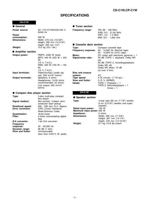
SPECIFICATIONS.
NAMES OF PARTS
OPERATION MANUAL.
DISASSEMBLY .........
REMOVING AND REINSTALLING THE MAIN PARTS.
ADJUSTMENT
TEST MODE
NOTES ON SCHEMATIC DIAGRAM ..
TYPES OF TRANSISTOR AND LED
BLOCK DIAGRAM ............................

SCHEMATIC DIAGRAM/WIRING SIDE OF P.W.BOARD. 20
WAVEFORMS OF CD CIRCUIT 42
TROUBLE SHOOTING 43

FUNCTION TABLE OF lC ..
FL SEGMENT ...................................................................................................................................................................... 55
PARTS GUIDE/EXPLODED VIEW

\ /

-
This document has been published to be used

SHARP CORPORATION tor alter sales service only.

The contents are subject to change without notice.

Page 2

CD-C1W,CP-C1W
SAFETY PRECAUTION FOR SERVICE MANUAL

WARNINGS
THE AEL (ACCESSIBLE EMISSION LEVEL) OF THE LASER POWER OUTPUT IS LESS THAN CLASS 1 BUT THE LASER
COMPONENT IS CAPABLE OF EMITTING RADIATION EXCEEDING THE LIMIT FOR CLASS 1. THEREFORE IT IS
IMPORTANT THATTHE FOLLOWING PRECAUTIONS ARE OBSERVED DURING SERVICING TO PROTECT YOUR EYES
AGAINST EXPOSURE TO THE LASER BEAM.
1-WHEN THE CABINET IS REMOVED, THE POWER IS TURNED ON WITDOUTA COMPACT DISC IN POSITION AND THE
PICK-UP IS ON THE OUTER EDGE THE LASER WILL LIGHT FOR SEVERAL SECONDS TO DETECT A DISC. DO NOT
LOOK INTO THE PICK-UP LENS.
2-THE LASER POWER OUTPUT OF THE PICK-UP UNIT AND REPLACEMENT SERVICE PARTS ARE ALL FACTORY
PRE-SET BEFORE SHIPMENT.
DO NOT ATTEMPT TO RE-ADJUST THE LASER PICK-UP UNIT DURING REPLACEMENT OR SERVICING.
3-UNDER NO CIRCUMSTANCES STARE INTO THE PICK-UP LENS AT ANY TIME.
4-CAUTION-USE OF CONTROLS OR ADJUSTMENTS, OR PERFORMANCE OF PROCEDURES OTHER THAN THOSE
SPECIFIED HEREIN MAY RESULT IN HAZARDOUS RADIATION EXPOSURE.

CAUTION Laser Diode Properties
Material: GaAlAs
Wavelength: 780 nm

. Emission Duration: continuous
APPANEIL A LASER DE cusse l .
Pnouucru LASER u: ELASE 1 Laser OUIPUI' max. 06 mW A

O This Mini Component System is classified as a CLASS
1 LASER product.

0 The CLASS 1 LASER PRODUCT label is located on
the rear cover.

BLASS I LASER PRODUCT

0 Use of controls or adjustments or performance of pro,
cedures other than those specified herein may result in
hazardous radiation exposure.

As the laser beam used in this compact disc player is m

harmful to the eyes, do not attempt to disassemble the WWW
cabinet. Refer servicing to qualified personnel only.

-W-\7\mm\u hulkilw mm mm xnixm
m l s-mtlm uuk at mktKll numb Nnk

VARO ! Avattaessa ja suojalukitus ohitettaessa olet alttiina nakymattomalle lasersateilylle. Ala katso sateeseen.
VARNING! Osynlig laserstralning nar denna del ar oppnad och sparren 5r urkopplad. Betrakta ej stralen.

VOLTAGE SELECTION

The voltage selector is located on the AC voltage selector box. If adjustment is necessary, use a screwdriver in order to turn
the selector in either direction until the correct voltage figure is displayed in the window next to the adjustment screw.

QACCAUOOIAWOO 92LC6RDA1387C

P =g
QACCBOOOSAWOO 92LC5RDT1699A

-;%

QACCEOOOSAWOO 92LPLUGOZ7

.flfiEE.

Figure 2 AC POWER SUPPLY CORD AND AC PLUG ADAPTOR
_ 2 _