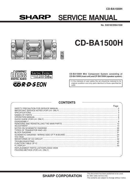
Sharp cd ba 1500 h service manual

This is the 68 pages manual for sharp cd ba 1500 h service manual.
Read or download the pdf for free. If you want to contribute, please mail your pdfs to info@audioservicemanuals.com.

Page: 1 / 68
left right
sharp cd ba 1500 h service manual

Extracted text from sharp cd ba 1500 h service manual (Ocr-read)


Page 1

CD-BA1500H

SHARP SERVICE MANUAL

No. S3018CDBA1500

CD-BA1500H

COMPACT
SAVING ENERGY CD-BA1500H Mini Component System consisting oi
STANDBY POWER 0 6W CD-BA1500H (mani unit) and CP-BA1 500H (speaker system).

CONSUMPTION
DIGITAL AUDIO

- In the interests of user-safety the set should be restored to its

original condition and only pans identical to those specified be
' ' used.

CONTENTS -

SAFETY PRECAUTION FOR SERVICE MANUAL
IMPORTANT SERVICE NOTES (FOR UK. ONLY) ..
SPECIFICATIONS
NAMES OF PARTS
OPERATION MANUAL.
QUICK GUIDE (FOR UK. ONLY)..
DISASSEMBLY ..............................
REMOVING AND REINSTALLING THE MAIN PARTS
ADJUSTMENT ...................................
NOTES ON SCHEMATIC DIAGRAM


TYPES OF TRANSISTOR AND LED. 20
BLOCK DIAGRAM ............................. 21
SCHEMATIC DIAGRAM / WIRING SIDE OF P.W.BOARD.

VOLTAGE

WAVEFORM
TROUBLESHOOTING .....
FUNCTION TABLE OF IC
FL DISPLAY .....................
REPLACEMENT PARTS LlST/EXPLODED VIEW
PACKING METHOD (FOR UK. ONLY)

-
This document has been published to be used

SHARP CORPORATION for after sales service only.

The contents are subject to change without notice.

Page 2

CD-BA1500H

SAFETY PRECAUTION FOR (For Europe)
SERVICE MANUAL

ll
LASER KLASSE 1 Hi

. . . _ LUOKAN f LASERLAITE
Precaution to be taken when replacing and serVIcing the KLASS 1 LASERAPPARAT

Laser Pickup. LASERTRiDV1

LASER TRIEDV 1

oooo
The AEL (Accessible Emission Level) of Laser Power Output 2:33:32: 02 Té,
forthis model is specified to be lowerthan Class | Requirements. 3:20:03: 0: _ 4
However, the following precautions must be observed during cuss I LASER PRODUCT 33:33:32 3:
servicing to protect your eyes against exposure to the Laser APPAREIL A LASER UE CLASSE l 22:05:? 2:

: °o

beam. PRODUETU LASER DE ELISE l

(1) When the cabinet has been removed, the power is turned
on without a compact disc. and the Pickup is on a position

outerthan the lead-in position, the Laserwill light forseveral Laser Diode Propemes
seconds to detect a disc. Do not look into the Pickup Lens. Material: GaAlAs

(2) The Laser Power Output of the Pickup inside the unit and Wavelength: 780 nm
replacement service parts have already been adjusted prior Em'SSO" Dmatmi CW'WOUS
to shipping. Laser Output max. 0.6 mW

(3) No adjustment to the Laser Power should be attempted
when replacing or servicing the Pickup.

(4) Under no circumstances look directly into the Pickup Lens
at any time.

(5) CAUTION - Use of controls or adjustments, or performance
of procedures other than those specified herein may result
in hazardous radiation exposure.

(For U.K.)

llllllllllllllllllllllllllllllllllllllllllllllll _-m
llllllllllllllllllllllllllllllllllllllllllllllll UN MU) OPHKA 1N 1!:th

lllllllillll Hifilllllllllllllllllllllllllfll

um mum NAKYMATKN mmumum
ALA TlllJUVA xx SEEN M AKA mm mm OPTISEN LATFIIILV LAM
\mvmmtsv . Lu MR mm )PPNAD

mam um I ; on: mmm H mm m Mm 0?ka
wsmwtm

CLASS 1 LASER PRODUCT

APPAREIL R USER DE CLISSE l
PRflDUCTfl LASER RE ELISE l

VAROlTUS! LAITTEEN KAVTrAMINEN MUULLA KUIN
TASSA
CAUTION KAVTTOOHJEESSA"MAINITULLA TAV ALLA SAATTAA
. ALTISTAA KAVTTAJAN TUHVALLISUUSLUOKAN 1
Use of controls, adjustments or performance of procedures In-MALE NAKVMATrtSMALLE LASERSATEILVLLE.
other than those specified herein may result in hazardous
radiation exposure. vARNiNG - OM APPARATEN ANVRNDs PA ANNAT sATT
AN |__DENNA BHUKSANVHISNING SPEciFICEHAs. KAN
As the laser beam used in this compact disc player is harmful ANVANDABEN UTSATTAS FOR __ OSVNLJG
to the eyes, do not attempt to disassemble the cabinet. Refer Ligggiméflm 50 OVERSKR'DER GHANSEN F0

IMPORTANT SERVICE NOTES (FOR U.K. ONLY)

WlTHSTANDING

Before returning the unit to the customer after completion of a VOLTAGE TESTER
repair or adjustment it is necessary forthefollowing withstand
voltage test to be applied to ensure the unit is safe for the AC b @-
customer to use. 13- our
Setting of Withstanding Voltage Tester and set. 9_ I: WT
Set name set value
SHORT-CIRCLHT CONNECT THE PROBE
Withstanding Voltage Tester AC powgn TO GND or CHASSIS
SCREW
Test voltage 4,240 VPEAK SUPP CORD
390° VRMS llllllllllllllllllllllllllllllllllllllllllllllll
_ llllllllll'lllllllllllllllllllllllll
Set time 6 secs
Set current(Cutoff current) 4 mA
Unit
Judgment
OK: The GOOD" lamp lights.
NG: The NG lamp lights and the buzzer sounds.

CHASSIS SCREW