Scott LT 110 Alignment

This is the 12 pages manual for Scott LT 110 Alignment.
Read or download the pdf for free. If you want to contribute, please mail your pdfs to info@audioservicemanuals.com.

Page: 1 / 12
left right
Scott LT 110 Alignment

Extracted text from Scott LT 110 Alignment (Ocr-read)


Page 1

Aligning the Tuner

Two methods are provided for aligning the
tuner. One is the unique EZ-A-LINE method
which eliminates the necessity of using test equip-
ment, while insuring top quality results. The sec-
ond method is the conventional process employing
standard laboratory techniques and instrumenta-
tion. This is outlined in the enclosed Service Bul-
letin.

For the EZ-A-LINE method the following items
are necessary: a special alignment tool, a small
screwdriver, an FM dipole antenna, a standard
audio cable, a CC .05 capacitor, and two alligator
clips, all of which are provided. You must provide
an amplifier and a speaker.

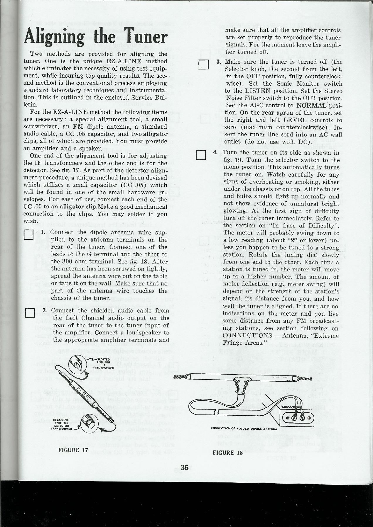
One end of the alignment tool is for adjusting
the IF transformers and the other end is for the
detector. See fig. 17. As part of the detector align-
ment procedure, a unique method has been devised
which utilizes a small capacitor (CC .05) which
will be found in one of the small hardware en»
velopes. For ease of use. connect each end of the
CC .05 to an alligator clip.Make a good mechanical
connection to the clips. You may solder if you
wish.

D1.

Connect the dipole antenna wire sup»
plied to the antenna terminals on the
rear of the tuner. Connect one of the
leads to the G terminal and the other to
the 300 ohm terminal. See fig. 18. After
the antenna has been screwed on tightly,
spread the antenna wire out on the table
or tape it on the wall. Make sure that no
part of the antenna wire touches the
chassis of the tuner.

2. Connect the shielded audio cable from
the Left Channel audio output on the
rear of the tuner to the tuner input of
the amplifier. Connect a loudspeaker to
the appropriate amplifier terminals and

SLDTTED
(ND roe

L r
YRANSFUWME n

szonomL
(no you
DEVECYOR

rnmsroRMEs

FIGURE 17

35

make sure that all the amplifier controls
are set properly to reproduce the tuner
signals. For the moment leave the ampli-
fier turned 03.

. Make sure the tuner is turned off (the

Selector knob, the second from the left,
in the OFF position, fully counterclock-
wise). Set the Sonic Monitor switch
to the LISTEN position. Set the Stereo
Noise Filter switch to the OUT position.
Set the AGC control to NORMAL posi-
tion. 0n the rear apron of the tuner, set
the right and left LEVEL controls to
zero (maximum counterclockwise). In-
sert the tuner line cord into an AC wall
outlet (do not use with DC).

Turn the tuner on its side as shown in
fig. 19. Turn the selector switch to the
mono position. This automatically turns
the tuner on. Watch carefully for any
signs of overheating or smoking, either
under the chassis or on top. All the tubes
and bulbs should light up normally and
not Show evidence of unnatural bright
glowing, At the first sign of difficulty
turn off the tuner immediately. Refer to
the section on In Case of Difficulty.
The meter will probably swing down to
a low reading (about 2 or lower) un-
less you happen to be tuned to a strong
station. Rotate the tuning dial slowly
from one end to the other. Each time a
station is tuned in, the meter will move
up to a higher number. The amount of
meter deflection (e.g., meter swing) will
depend on the strength of the stations
signal, its distance from you, and how
well the tuner is aligned. If there are no
indications on the meter and you live
some distance from any FM broadcast-
ing stations, see section following on
CONNECTIONS g Antenna, Extreme
Fringe Areas.

counzcnou or mum) DWOLE "rum

FIGURE 18

Page 2

Normal areas - if you are in an average
listening area, you will tune in some
strong stations that make the meter
move up over 4 and some weak sta-
tions that barely manage to wiggle the
meter at all. Tune in one of the strong
stations, setting the tuning dial so that
the meter is at its highest position for
that particular station.

Extreme fringe areas - if you live many
miles from any transmitter, you may
find that it is impossible to note even
a wiggle on the meter. Try raising the
antenna off the table and taping it to the
wall. If that does not help, connect the
tuner to the antenna wire coming from
an outdoor television antenna. A final
approach is to use the amplifier as a
guide. Turn the input selector of the
amplifier to the tuner input. Turn up
the left channel level control on the rear
of the tuner. Adjust the volume control
of the amplifier so that the sound from
the tuner itself can be heard. Turn the
tuning knob of the tuner until a station
is audible. It will undoubtedly be very
distorted, faint, and noisy. Start the
alignment procedure at this position
Once meter deflection occurs, readjust
the tuning knob so that the meter is at
its highest reading for the station.
Ignore the sound quality from then on
(in fact, you can turn down the vol»
ume); however, you may find that in
making the following adjustments the
presence of some volume will be helpful.
You will find that when the volume is
approximately at its highest point, you
will be very close to maximum meter de~
fiection. This method of locating the
peak point in the can will eliminate the
necessity of going from one end of the
can to the other. THE SOUND AT THIS
POINT WILL BE DISTORTED. DO
NOT MAKE REFERENCE TO THE
SOUND QUALITY.

Should neither of the above methods
give you a meter reading, the following
procedure should be used:

Connect the Alligator clips to each end
of an 11 Wire. Connect one clip to Pin
3, D3MA on the Z-FM-l. Connect the
other clip to Pin 1, D40. Connect another
wire from Pin 4, D4C to any good ground
point on the tuner. (You can run the
end of the wire through one of the holes
in the bottom flange of the set and twist

it around.) You should now be able to
locate at least one station which gives a
meter reading of between 0 and 2. Now
start aligning your tuner. AS SOON AS
YOU HAVE ALIGNED THE TUNER
ENOUGH TO SUSTAIN A METER
READING WITHOUT THE USE OF
THESE TWO WIRES - REMOVE
THE WIRES.

If this procedure gives you no meter
reading, refer to the section on In Case
of Difliculty.

. Carefully adjust the tuning knob so that

the meter is at its highest position for
the station tuned in.

N OTE: The passage overhead of an air-
plane will cause the meter indicator to
swing up and down. Hold up the align-
ment until this stops. Set the tuner on
its end with the black transformer side
down, and the front panel facing you
(see fig. 19).

[:1 6. Insert the IF alignment tool (see fig. 17)

D7.
D8.

36

into the top (above the chassis) of T2
(skip T1 for the moment) until the end
of the tool makes contact with the tuning
slug inside. The slug may be over a half
inch inside the transformer. Rotate the

tuning slug slowly back and forth with
the alignment tool while carefully
watching the tuning meter for the high-
est reading. At this time the meter ac-
tion may be small, so you have to look
carefully to insure getting the highest
point. You will have to rotate the slug
both clockwise and counterclockwise to
locate this maximum position. A scrap-
ing noise will be audible as the slug is
turned. This is normal. At the extreme
clockwise and counter-clockwise position
of the slug there is a stop beyond which
you should not turn. Do no force beyond
this point as this will damage the trans-
former cans. It is possible for the maxi-
mum reading to occur at a stop.

Insert the IF alignment tool into the bot-
tom (below the chassis) of T2, and ro-
tate for highest reading on the meter.

Carefully readjust the tuning knob to
make sure that the station is still tuned
to the maximum reading on the meter.
Insert the IF alignment tool into the top
of T3 and rotate for maximum meter
reading.