Scott 370B Sevice Bulletin

This is the 6 pages manual for Scott 370B Sevice Bulletin.
Read or download the pdf for free. If you want to contribute, please mail your pdfs to info@audioservicemanuals.com.

Page: 1 / 6
left right
Scott 370B Sevice Bulletin

Extracted text from Scott 370B Sevice Bulletin (Ocr-read)


Page 1

111 Powdermill Road, Maynard, Mass.

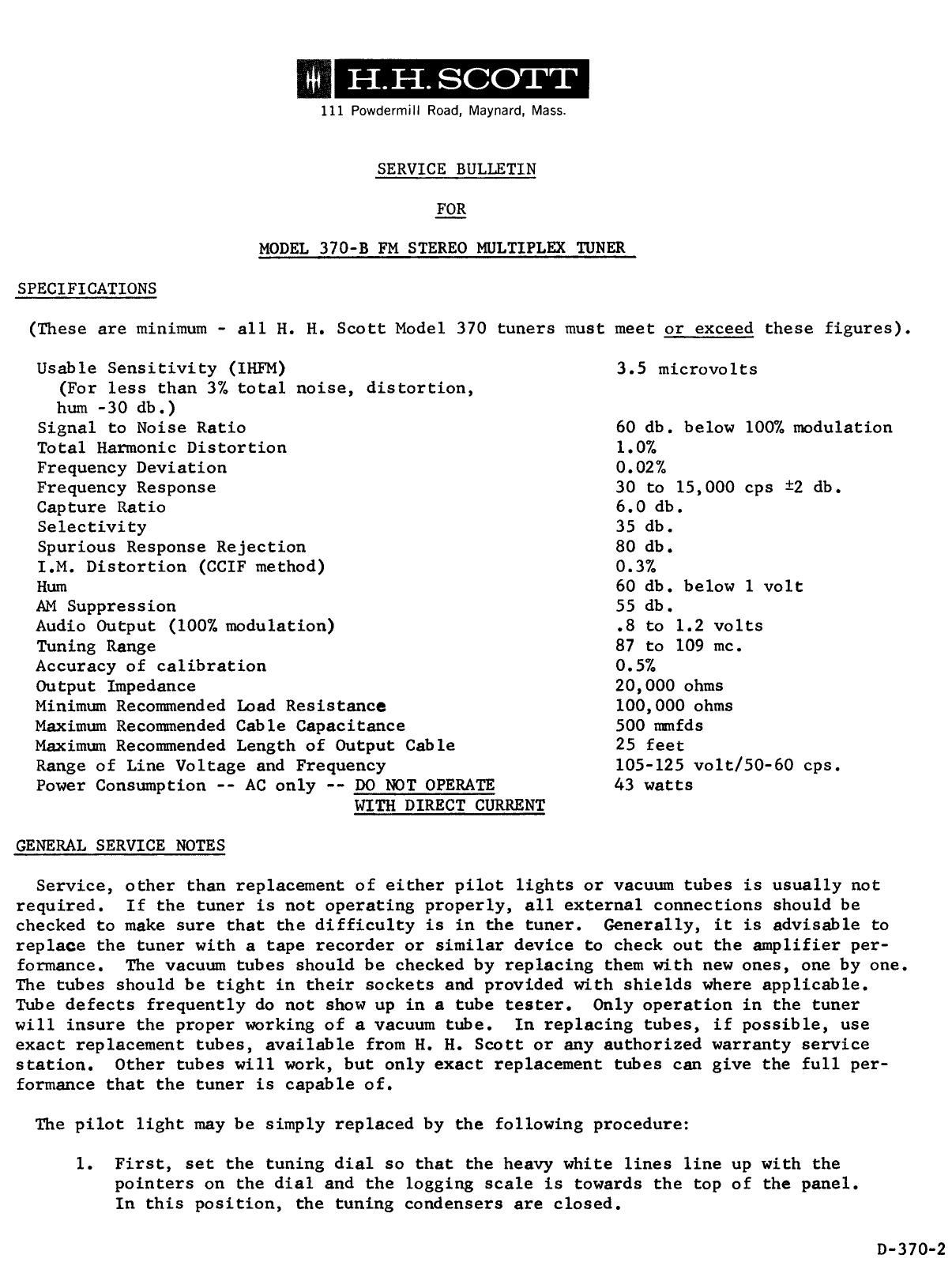
SERVICE BULLETIN
g3
MODEL 370-3 FM STEREO MULTIPLEX TUNER
SPECIFICATIONS

(These are minimum - all H. H. Scott Model 370 tuners must meet or exceed these figures).

Usable Sensitivity (IHFM) 3.5 microvolts
(For less than 3% total noise, distortion,
hum -30 db.)
Signal to Noise Ratio 60 db. below 100% modulation
Total Harmonic Distortion 1.0%
Frequency Deviation 0.02%
Frequency Response 30 to 15,000 cps i2 db.
Capture Ratio 6.0 db.
Selectivity 35 db.
Spurious Response Rejection 80 db.
I.M. Distortion (CCIF method) 0.3%
Hum 60 db. below 1 volt
AM Suppression 55 db.
Audio Output (100% modulation) .8 to 1.2 volts
Tuning Range 87 to 109 me.
Accuracy of calibration 0.5%
Output Impedance 20,000 ohms
Minimum Recommended Load Resistance 100,000 ohms
Maximum Recommended Cable Capacitance 500 mmfds
Maximum Recommended Length of Output Cable 25 feet
Range of Line Voltage and Frequency 105-125 volt/50-60 cps.
Power Consumption -- AC only -- DO NOT OPERATE 43 watts

WITH DIRECT CURRENT

GENERAL SERVICE NOTES

Service, other than replacement of either pilot lights or vacuum tubes is usually not
required. If the tuner is not operating properly, all external connections should be
checked to make sure that the difficulty is in the tuner. Generally, it is advisable to
replace the tuner with a tape recorder or similar device to check out the amplifier per-
formance. The vacuum tubes should be checked by replacing them with new ones, one by one.
The tubes should be tight in their sockets and provided with shields where applicable.
Tube defects frequently do not show up in a tube tester. Only operation in the tuner
will insure the proper working of a vacuum tube. In replacing tubes, if possible, use
exact replacement tubes, available from H. E. Scott or any authorized warranty service
station. Other tubes will work, but only exact replacement tubes can give the full per-
formance that the tuner is capable of.

The pilot light may be simply replaced by the following procedure:
1. First, set the tuning dial so that the heavy white lines line up with the

pointers on the dial and the logging scale is towards the top of the panel.
In this position, the tuning condensers are closed.

D-370-2

Page 2

2.

Unscrew and remove the tuning knob and dial. This will permit access to the pilot light which is a VPL-lZ
bulb.

After the bulb has been replaced, use the following procedure:

1.

2.

3.

Close the condenser plates by rotating the condenser to the extreme counter-clockwise position.

Replace the dial, lining up the heavy white lines of the dial with the pointers and keeping the logging
scale toward the top of the front panel.

Replace the tuning knob.

ALIGNMENT INSTRUCTIONS FOR FM SECTION

Note: No attempt should be made to align the tuner or repair it unless the person so doing has had extensive

l.

7.

experience in tuner alignment and repair procedures and has the necessary laboratory equipment. Without
proper experience or equipment, the repairman may seriously damage the tuner.

Equipment required: VTVM (AC), FM Signal Generator (must be Measurements ZIOAB or equivalent), Oscilloscope,
400 cps null, and insulated alignment tools.

Equipment set-up: Connect signal generator directly to the 300 ohm antenna input of the tuner using a match-
ing impedance network if necessary. The Channel A audio output of the 370 then feeds into the (+00 cps null
and from the null to the oscilloscope and VTVM in parallel. If no null is available (a schematic for making
one of these very simple and useful devices is available from the Engineering Dept.) the tuner can still be
serviced. However, it will not be possible to measure the tuner's "Usable Sensitivity" as per IHFM standards,
or align the detector.

Allow tuner and test equipment to warm up fully before beginning alignment. Adjust line voltage for 117
volts. Remove bottom cover of tuner. Always tune primary and secondary of LF. transformers at the same
time, using one alignment tool in each hand. Set 370 Selector Switch to Mono.

Set generator and tuner for 92 mc. Generator should be modulating a 400 cps signal at 75 kc deviation.
Adjust output of generator so that a barely adequate sine wave appears on the scope (on the order of 5 to 10
microvolts). The null filter should be switched out of the setup, so the tuner is feeding directly to the
VTVM and scope. Peak the IF's and the primary of the ratio detector (the bottom slug) for

maximum reading on the VTVM.

Increase generator output to 1000 microvolts and switch the 400 cps null into the circuit. 'lune ratio
detector secondary (top slug) for minimum reading on the VTVM.

Return generator output back down to 5 to 10 microvolts. Adjust antenna coil (under chassis) for maximum
output. Tune generator and tuner to 106 me. with same output and deviation, and adjust antenna trimmers (on
top - FM ANT.) for maximum output. Repeat this operation until best results are obtained.

If calibration is off, repeat "6" except adjust oscillator coils (under chassis) for correct tracking at 92
mo. and oscillator trimmer (FM OSC - on top) for correct tracking at 106 mc.

MISCELLANEOUS SERVICE PROCEDURES AND TESTS - (Qualified technicians only)

Note: Replace bottom plate before testing.

1.

Test for IHFM Usable Sensitivity measurements: Use 117 volt regulated line, set generator and tuner at 92
me, with 10 microvolt input. Take a reference reading on the db. scale and check for 38 db. or more reduction
in output with 400 cycle null filter switched in to setup. Repeat at 106 me. If specification is not met,
tuner should be realigned and tubes checked. It is very important that the null filter be carefully adjusted
so that it is at exactly the same frequency as the 400 cps modulation being fed in. otherwise, it will be
impossible to obtain stated sensiti-