Scott 330C Schematic

This is the 2 pages manual for Scott 330C Schematic.
Read or download the pdf for free. If you want to contribute, please mail your pdfs to info@audioservicemanuals.com.

Page: 1 / 2
left right
Scott 330C Schematic

Extracted text from Scott 330C Schematic (Ocr-read)


Page 1

6/5/56

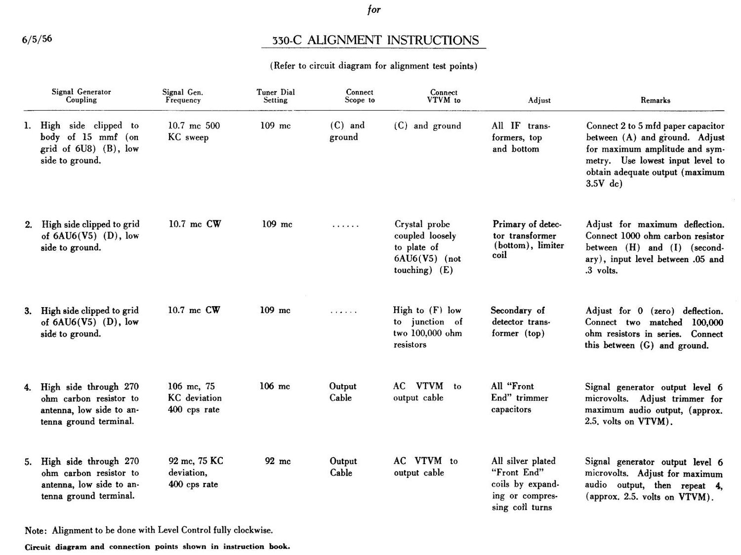
350C ALIGNMENT INSTRUCTIONS

(Refer to circuit diagram for alignment test points)

Signal Generator Signal Gen. Tuner Dial Connect Connwt
Coupling Frequency Setting Scope to VTVM to Adjust Remarks

1. High side clipped to 10.7 me 500 109 me (C) and (C) and ground All IF trans- Connect2t05mfd paper capacitor
body of 15 mmf (on KC sweep ground formers, top between (A) and ground. Adjust
grid of 6U8) (B), low and bottom for maximum amplitude and sym-
side to ground. metry. Use lowest input level to

obtain adequate output (maximum
3.5V dc)

2. High side clipped to grid 10.? me CW 109 me ...... Crystal probe Primary of detec- Adjust for maximum deflection.
of 6AU6(V5) (D), low coupled loosely tor transformer Connect 1000 ohm carbon resistor
side to ground. to plate of (bottom), limit" between (H) and (I) (second-

6AU6(V5) (not 0011 ary), input level between .05 and
touching) (E) .3 volts.

3. High side clipped to grid 10.7 mc CW 109 me ...... High to (F) low Secondary of Adjust for 0 (zero) deflection.
of 6AU6(V5) (D), low to junction of detector trans- Connect two matched 100,000
side to ground. two 100,000 ohm former (top) ohm resistors in series. Connect

resistors this between (C) and ground.

4. High side through 270 106 me, 75 106 Inc Output AC VTVM to All Front Signal generator output level 6
ohm carbon resistor to KC deviation Cable output cable End trimmer microvolts. Adjust trimmer for
antenna, low side to an- 400 cps rate capacitors maximum audio output, (approx.
tenna ground terminal. 2.5. volts on VTVM).

5. High side through 270 92 me, 75 KC 92 me Output AC VTVM to All silver plated Signal generator output level 6
ohm carbon resistor to deviation, Cable output cable Front End microvolts. Adjust for maximum
antenna, low side to an- 400 cps rate coils by expand- audio output, then repeat 4,

tenna ground terminal.

Note: Alignment to be done with Level Control fully clockwise.

Circuit diagram and connection points shown in instruction book.

ing or compres-
sing coil turns

(approx. 2.5. volts on VTVM).