Scott 325R 335R Service Manual

This is the 14 pages manual for Scott 325R 335R Service Manual.
Read or download the pdf for free. If you want to contribute, please mail your pdfs to info@audioservicemanuals.com.

Page: 1 / 14
left right
Scott 325R 335R Service Manual

Extracted text from Scott 325R 335R Service Manual (Ocr-read)


Page 1

SC01T 325R/335R

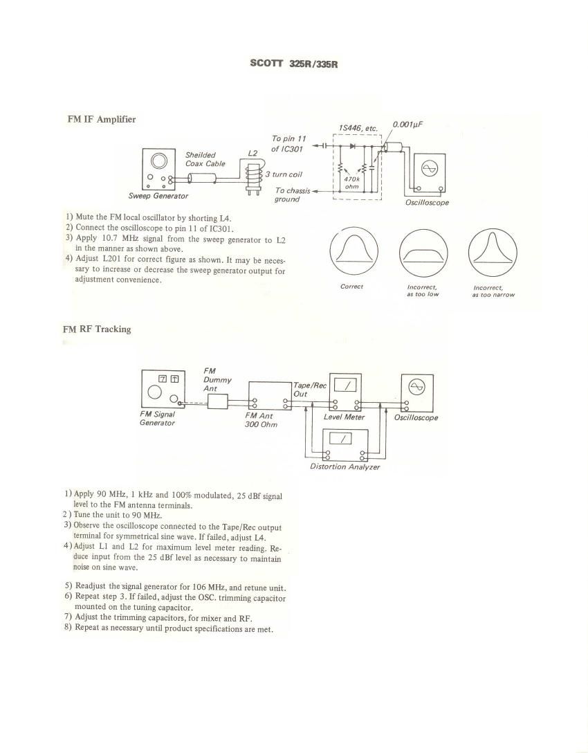
PM IF Amplifier (100,;
To pin 71
Sheilded L2 Of [C301
© Coax Cable
0 o 8 3 turn coil
° ° To chassis - - '0 O
Sweep Generator ground r. ______ J

Oscilloscope

I) Mute the FM local oscillator by shorting L4.
2) Connect the oscilloscope to pin 11 of IC301.

3) Apply 10] MHz signal from the sweep generator to L2
in the manner as shown above.

4) Adjust L201 for correct figure as shown. It may be neces-
sary to increase or decrease the sweep generator output for

adjustment convenience.

Correct Incorrect, Incorrect,
as too low a: too narrow

PM RF Tracking

FM
a a gummy Tape/Rev:
0 nt Out
0 __V 3 c ' 0
FM Signal FM Ant Level Meter Oscilloscope
Generator 300 Ohm

Distortion Analyzer

1) Apply 90 MHz, 1 kHz and 100% modulated, 25 dBf signal
level to the FM antenna terminals.

2) Tune the unit to 90 MHz.

3) Observe the oscilloscope connected to the Tape/Rec output
terminal for symmetrical sine wave. It failed, adjust L4.

4)Adjust L1 and L2 for maximum level meter reading. Re-

duce input fmm the 25 dBf level as necessary to maintain
noise on sine wave.

5) Readjust the signal generator for 106 MHz, and retrme unit.

6) Repeat step 3. If failed, adjust the OSC. trimming capacitor
mounted on the tuning capacitor.

7) Adjust the trimming capacitors, for mixer and RF.

8) Repeat as necessary until product specifications are met.

Page 2

Center Tuning Indicator (LED Pointer Assy.)

Connect DMM (switched to DC volts) between chassis and pin
15 of IC201. Tune receiver to signal generator with output
level set at 65 dBf. Carefully tune for lowest AGC voltage
(approx. 2.5).

FM Distortion
With unit connected as above for tuning indicator adjustment,
adjust T203 for minimum harmonic distortion.

FM Signal Strength Display

1) At 98 MHZ, with receiver connected and tuned to FM gen-
erator, apply 65 dBf signal to unit antenna.

2) Adjust R217 until all five LEDs are lighted.

Mute Threshold Adjust
1) At 98 MHz, 20 dBf signal level, and setup connected as
above, tune unit with mute switch in the OFF position.

Multiplex Pilot Adjust

1) Apply 98 MHZ, 65 dBf signal to the unit with no modula-
tion.

Stereo Separation

1) Apply 98 MHz, 65 dBf left channel signal to the unit modu-
lated with 1 kHz, 9% pilot signal.

2) Connect a digital voltmeter to the right channel Tape/Rec
output terminal.

3) Adjust R315 for minimum leakage (minimum level) on the
voltmeter.

AM IF Amplifier

1) Apply 455 kHz sweep generator output to the Unit AM
antenna terminal.

2) Connect scope to pin number 12 of 1C3.

3) Adjust T8 to obtain maximum and symmetrical display as
shown.

AM Tracking

1) Apply 600 kHz, 30% modulated with 1 kHz to the AM bar
antenna. See test setup figure. (Distance between the AM
bar antenna and emitting loop antenna should be 2 feet.)

2) Adjust signal generator output so that a sine wave appears
on the scope.

Reconnect DMM to terminals 603 and 604 on display board
3014-5138108. Adjust T202 for zero volts on DMM.

Since there is some interaction between coil settings repeat
center-tune and distortion adjustments for optimum results.

3) Reduce RF generator output to minimum, tune receiver
off station and adjust R621 on display board until both
green LEDS in pointer assembly are turned ON and all
signal strength LEDs are turned OFF.

NOTE: R217 replaced with fixed resistor in some produc-
tion units.

2) Switch MUTE ON and adjust R220 until FM output is
muted.

2) Adjust R317 for 76 kHz reading on the frequency counter
connected between TP and chassis ground. A deviation of
+200 Hz is acceptable.

4) Apply 98 MHz, 65 dBf right channel signal to the unit mod-
ulated same as step 1.

5) Move digital voltmeter to the left channel Tape/Rec output
terminal.

6) Check for approximately the same leakage as in step 3.

3) Adjust L102 for maximum audio output on the digital volt-
meter connected parallel with the scope. When turning
core, always adjust signal generator output to maintain low
input level. Do not change voltmeter range. Moreover, al-
ways keep the generator output as low as possible to avoid