Scott 312C Service Manual

This is the 8 pages manual for Scott 312C Service Manual.
Read or download the pdf for free. If you want to contribute, please mail your pdfs to info@audioservicemanuals.com.

Page: 1 / 8
left right
Scott 312C Service Manual

Extracted text from Scott 312C Service Manual (Ocr-read)


Page 1

H. H. SCOTT, INC.

111 POWDER MILL RD., MAYNARD, MA55., 01754

Service Bulletin
for
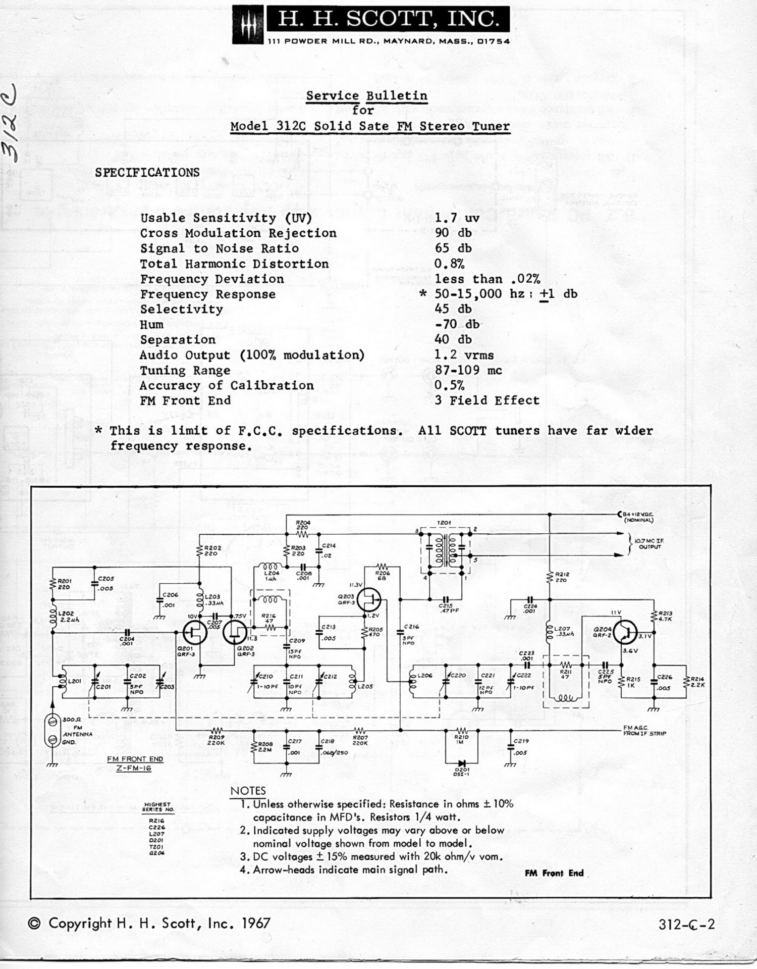
Model 312C Solid Sate FM Stereo Tuner

3/2 C,

SPECIFICATIONS
Usable Sensitivity (UV) 1.7 uv
Cross Modulation Rejection 90 db
Signal to Noise Ratio 65 db
Total Harmonic Distortion 0.8%
Frequency Deviation less than .02%
Frequency Response * 50-15,000 hz: id db
Selectivity 45 db
Hum -70 db
Separation 40 db
Audio Output (100% modulation) 1.2 vrms
Tuning Range 87-109 mc
Accuracy of Calibration 0.5%
FM Front End 3 Field Effect

* This is limit of F.C.C. Specifications. All SCOTT tuners have far wider
frequency response.

a {34 never;
(mmmL)


lO.7 MC IF
007M
-

C22!


R2
{ZK

'2 Pi
N PO


FM ARC.
MM IF STRIP

-‚¬219

FM FRQNT END


Z-FM-IG
NOTES
25:55,; l. Unless otherwise specified: Resistance in ohms i10%

Rm capacitance in MFD's. Resistors 1/4 watt.

3:: 2. Indicated supply voltages may vary above or below

3:3: nominal voltage shown from model to model.

a 3. DC voltages i 15% measured with 20k ohm/v vom.

4. Arrow-heads indicate main signal path. FM pm" End

© Copyright H. H. Scott, Inc. l967 5312-62-2

Page 5

AUXILIARY AGC.
TO FRONT END

"I
a;

SIGNAL STRENGTH
- METER + -1

___6;__._________

l3

il 0
°:°:
- R306
77 $4.
(3301

9304 §R305 §R303 C3°3 R307

2.2K 47K 330 .03 220

F-_----____----

fl

2.241 It R302

L [ox

W

+ c301
.- . II R30!
3710/20 c3I4 "3°"
.00:
I777 rm

ran-1:"?- ------+ -- -- -

AGC. Ase. AGC.
no 7 MHz +l2VDC +I2voc To mean-r
rr'mpu'r (nor/aims.) (NOMINAL) EN
3+ DISCONMECT
----- 0 SOUILCH 8+
HIGHEST SERIES (232: owrrso was» useo)
NUMBERS
0
FM IF AMPLIFIER :3; NOTES
0304 I. UNLESS omeawnsr specumo: RESISTANCE m owstnoy.
L30: RESISTORS '12 WATT, CAPACITANCE m MFD'S.
7304
3305 2.o.c. VOLTAGES £157. MEASURED wma 20 Kn/v vo M.

3. INDICATED SUPPLY VOLTAGES MAY VARY ABOVE OR BELOW
NOMINAL VOLTAGE SHOWH FROM MODEL TO MODEL.

4. ARROWHEADS INDICATE MAIN SIGNAL PATH.

8.2 PC Board Component Layout with Resistance Measurements

Resistance Measurements

Note

1) All measurements made with PC boards wired
into completed tuner, with line cord disconnected
(power mains disconnected).

2) All resistance measurements made with a Triplett
Model 630 VOM.

3) Negative side of VOM battery to ground.

4) All controls set as below.

METER function switch - Center Tuning
FUNCTION rotary switch -Off

SELECTOR rotary switch - Automatic Stereo,
Muting-OH

Stereo Separation controls - set for maximum sepa-
ration

LEVEL controls -both maximum clockwise

\