Scott 310E Service Bulletin

This is the 7 pages manual for Scott 310E Service Bulletin.
Read or download the pdf for free. If you want to contribute, please mail your pdfs to info@audioservicemanuals.com.

Page: 1 / 7
left right
Scott 310E Service Bulletin

Extracted text from Scott 310E Service Bulletin (Ocr-read)


Page 1

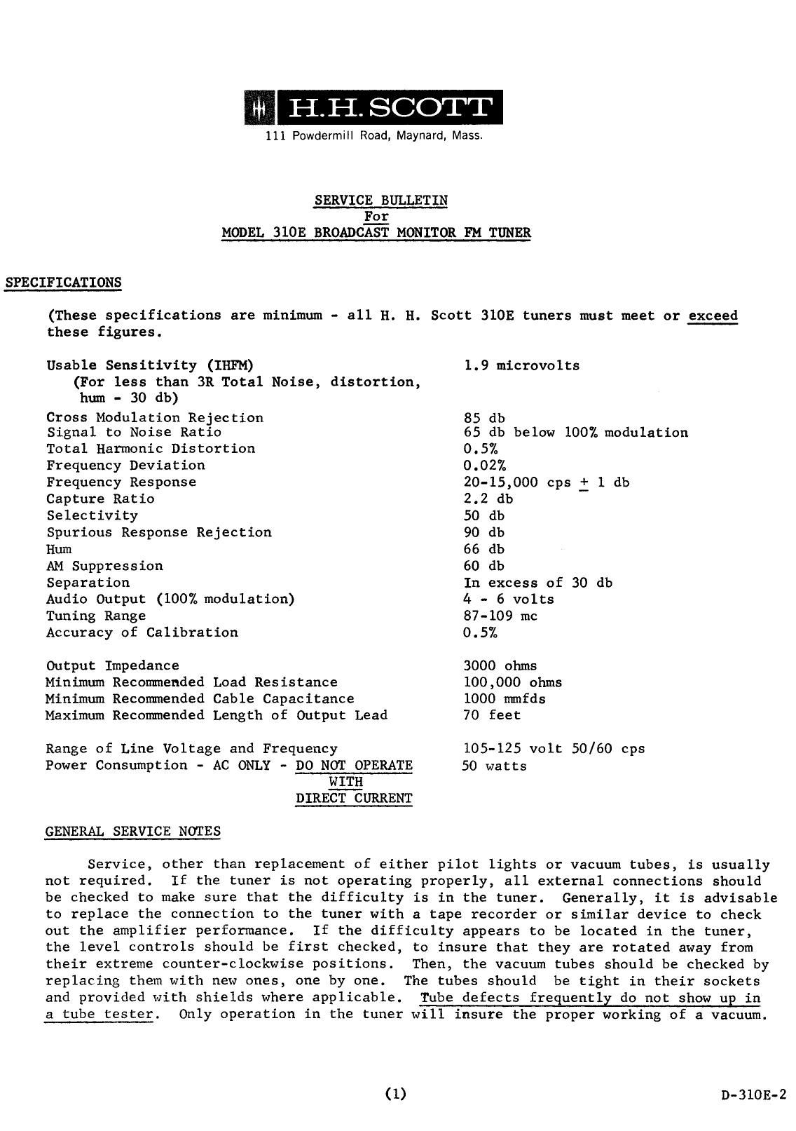
111 Powdermill Road, Maynard. Mass.

SERVICE BULLETIN
For
MODEL 310E BROADCAST MONITOR FM TUNER

SPECIFICATIONS

(These specifications are minimum - all H. H. Scott 310E tuners must meet or exceed

these figures.

Usable Sensitivity (IHFM)
(For less than 3R Total Noise, distortion,
hum - 30 db)

1.9 microvolts

Cross Modulation Rejection 85 db

Signal to Noise Ratio 65 db below 100% modulation
Total Harmonic Distortion 0.5%

Frequency Deviation 0.02%

Frequency Response 20-15,000 cps : 1 db
Capture Ratio 2.2 db

Selectivity 50 db

Spurious Response Rejection 90 db

Hum 66 db

AM Suppression 60 db

Separation In excess of 30 db
Audio Output (100% modulation) 4 - 6 volts

Tuning Range 87-109 mc

Accuracy of Calibration 0.5%

Output Impedance 3000 ohms

Minimum Recommended Load Resistance 100,000 ohms
Minimum Recommended Cable Capacitance 1000 mmfds

Maximum Recommended Length of Output Lead 70 feet

Range of Line Voltage and Frequency
Power Consumption - AC ONLY - DO NOT OPERATE
WITH
DIRECT CURRENT

105-125 volt 50/60 cps
50 watts

GENERAL SERVICE NOTES

Service, other than replacement of either pilot lights or vacuum tubes, is usually
not required. If the tuner is not operating properly, all external connections should
be checked to make sure that the difficulty is in the tuner. Generally, it is advisable
to replace the connection to the tuner with a tape recorder or similar device to check
out the amplifier performance. If the difficulty appears to be located in the tuner,
the level controls should be first checked, to insure that they are rotated away from
their extreme counter-clockwise positions. Then, the vacuum tubes should be checked by
replacing them with new ones, one by one. The tubes should be tight in their sockets
and provided with shields where applicable. Tube defects frequently do not show up in
a tube tester. Only operation in the tuner will insure the proper working of a vacuum.

(1) 9-3105-2

Page 2

Tuning Dial Pilot Light Replacement:

1.

2.

First set the tuning dial so that the heavy white lines line up with the
pointers on the dial and the logging scale is towards the top of the panel.
In this position, the tuning condensers are closed.

Unscrew and remove the tuning knob and dial. This will permit access to the
pilot light which is a #47 bulb.

After the bulb has been replaced, use the following procedure:

1.

2.

Close the condenser plates by rotating the condenser to the extreme counter-
clockwise position.

Replace the dial, lining up the heavy white lines of the dial with the pointers
and keeping the logging scale toward the top of the front panel.

Meter and Indicator Pilot Light Replacement:

1. Remove the pilot light assembly by inserting a sharp instrument (a screw driver
or knife) between the Control Shield and the Assembly Clip.
2. Remove the old bulb and install the new #47 bulb.
3. Reinstall the light assembly by snapping it into the hole.
TEST PROCEDURE
figgg: No attempt should be made to align the tuner or repair it unless the person

so doing has had extensive experience in tuner alignment and repair procedures
and has the necessary laboratory equipment. Without proper experience or
equipment, the repairman may seriously damage the tuner.

Equipment Needed:

VTVM (AC)

Oscilloscope

VOM

Distortion Meter

FM Signal Generator (must be measurements ZlOAB or equivalent)
MX Generator

Audio Generator

15 kc Low Pass Filter

Insulated Alignment Tools

Set Controls to the Following:

Level pots Max cw
Separation pots Max ccw
Mono Threshold (top) Max cw
Stereo Threshold (top) Max cw
Comp. phase adj. Max cw
AGC sw. Normal

Dynaural Squelch (front) Max ccw ('0')
Stereo Threshold (front) Max ccw ('0')
Selector sw. MONO
Function sw. Normal

(2)