Scott 299 Schematic

This is the 28 pages manual for Scott 299 Schematic.
Read or download the pdf for free. If you want to contribute, please mail your pdfs to info@audioservicemanuals.com.

Page: 1 / 28
left right
Scott 299 Schematic

Extracted text from Scott 299 Schematic (Ocr-read)


Page 1

¢z_

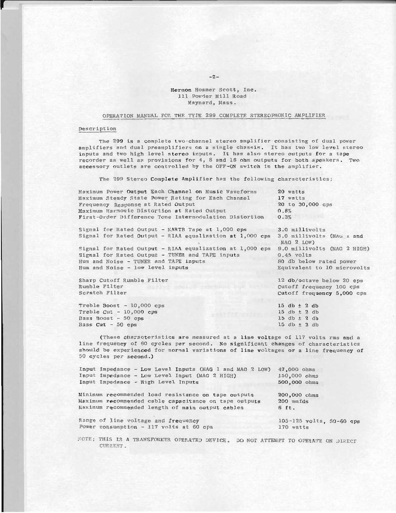
Hermon Holmer Scott, Inc.
111 Powder Mill Road
Maynard, Mass.

OPERATION MANUAL FOR THE TYPE 299 C(HPLETE STEREOPHONIC AMPLIFIER

Description

The 299 is I complete {watchannel stereo amplifier canalsting of dual power

amplifiers and dual preamplifiere On a single chastis.
inputs and two high level stereo inputs.
recorder as well as provlsions for 4,

It has two low level stereu
It has also stereo outputs for a tape
8 and 16 ohm outputs tor both speakers.

Two

accesflary outlets are controlled by the OFF»0N switch in the amplifier.

The 299 Steren Complete Amplifier has the following characteristics:

Maximum power Output Each channel on Music Waveforms
nnximum steady State Power Rating for Each Channel
Frequency Response at Rated Output

Maximum Harmonlc Distortion at Rated Output
First-Order Difference Tone lntermndulation Distortion

Signal for Rated Output - KART? Tape at 1,000 cps

Signal for Rated output - RIAA equalization at 1,000 cps
Signal for Rated Output - RIAA equalization at 1,000 cps
Signal for Rated Output ~ TUNER and TAPE inputs

Hum and Noise
Hum and Noise «

- TUNER and TAPE inputs
low level inputs

Sharp Catoti Rumble Filter
Rumble Filter
Scratch Filter

Treble Boost ~ 10,000 cps

Treble Cut - 10,000 cps
Bass finest ~ 50 cps
Bass Cut - 50 cps

20 Watts

17 watts

20 to 30,000 cps
0.8%

0.3%

3.0 mlllivolts

3.0 millivolts (NAU 1 and
MAG 2 Low)

9.0 millivolts (MAG 2 HIGH)
0.45 volts

80 db below rated power
Equivalent to 10 microvolts

12 dhxoctlve below 20 cps
Cutoff frequency 100 cps
Cutoff frequency 5,000 Cps

15 db 3 2 db
15 db t 2 db
15 db 2 2 db
15 db 1 2 db

(These characteristics are measured at a line voltage of ll? volts rns and a

llne frequency of 60 cycles per second.

No significant changes of characteristics

should be experienced for normal variations of line valtages or a line frequency of

50 cycles per second.)

Input Impedance - Low Level lnputs (MAG l and MAG 2 LOW)
Input Impedance - Low Level Input (BAG 2 HIGH)
Input Impedance - High Level Inputs

Mlnimum recommended load resistance on tape outputs
Maximum recommended cable capacitance on tape outputs
Maximum recommended length of main output cables

Range of llne voltage and frequency
Power cansumptinn - 117 volts at 60 ans

H; THIS IS a TRANSFORMER OPERATED DEVXCE.
CURPEVT.

47,000 ohms
150,000 ohms
500,000 ohms

200,000 ohms
200 mmids
6 ft.

105-125 volts, 50-60 cps
170 watts

DC! NOT ATTEMPT TO OPERATE ON JIflECl

Page 2

IIIIIm-IIl-Il

-3_
giQACKINQ

carefully remove the amplifier from its carton. Do not force any of the pack-
ing material or tuhe breakage y result.

If there is any damage to the amplifier, report it to your dealer imredialcly.
If your dealer shipped the nnplifier to you, report the damage to the shinplng company
an snon as noqslble. Failure to report tn? danage lnmculately may void any claim
against tnp shipping company. Remember that the warranty covers only de'ects due
to faulty workmannhlp or components. Rhipplng damage is not covered in the warranty.

Make sure the followlng necessaries have been included in the carton: Panel
Mounting Template, Package of Mnuntlng Hardware, Warranty Card, and Connecting Cable;
Be furs to send the warranty card to H. H. Scott, Inc. 50 that your instrument may be
registered in our warranty {118).

mmugnon;
l. Ventilation and Mounting
NOTE: FAILURE TO WUVILHE PROPER VENTILATION WILL '?ll(l,'l'EN THF LIFE OF THE AMPLIFIER.

It the amplifier ls to he mounted in the metal or wood accessory case designed
for it, be sure to leave a as a Will. The ventilating louvres or grille must not he covered, and it 15 desirable
to allow a space of 4 inches between the {on of the amplifier and any shelf or horizon-
tal surface over it.

I! the amplifier is to be panel-mounted or installed in custom cabinetry, be
sure to leave ane side at the hack of the cabinet open for adequate ventilation. In
this case as well, be cure tn leave a clearance of at least 4 mches above the amplh
rlcr to any hnrizontal surface. Due to the hear produced, tuner: will drlft if they
fire mounted above the ampleler. It is recommended that the tuner be mcunted below
or beside the amplitler.

Vertical mounting of this amplifier l5 not recommended. However, if the ampli-
Iler must be mounted vertically, 1: may be done providing blowers are used an the output
and rectifier tubes with proper escape for the air stream. At no time should the tempera-
ture on the chassis exceed l25 degrees F.

In order to make a panel mounting in a custom installatlon, apply the following
procedure:

A. Locate a supporting shelf in a cabinet at the height at which the
amplillcr is to he positlnned, and mark the edge at which the upper
surface of the supporting shelf meets the panel.

3. Using [his line as a guide, place the mounting template so that the
lower edge of the cutout Coincide$ with this line.

C. xark the 5120 cf the autumn and carefully cuL the Opening as Indi-
cated on the template.

1). Slide the a-unlillcz' m from the front so that it rests on a shelf.

Thc front panel shnuld aumgietely savor the openxnp.

Page 10

_._
gem

firm-nos or pxcxvps

The manufacturer's dlrectlons should be followed carefully in all case;. we are
listing some precautions and wuggcsttons here tn aid the user when such instructions
are absent or incomplete.

h. The cable lengths on phonograph cartrldges should be kept as short ac possible
to mlnlnize qhunt capacity whlch may cnuse high fequency peaks or roll-off and also
mihlmtze hum and noise plckup. At the same time, low capacity shielded cable should
be used to reduce shunt capacitance. lt is usually not wise to extend the total length
of cable from the phonograph ylckup to the amplifier more than slx feet.

2. There are several causes of hum and noise pickup. These can be isolated by the
process outllned below.

(I) SYHPTOM _ Loud hum and no slgnal from the phonograph cable when plugged
into the nupllfler; nu hum when the cable is removed from the amplifier.

Thls is usually due to a poor connection, broken solder julnt, broken
lead or frayed Vlre. Check the phonograph cables and plckup's leads
and connections.

(2) SYnPTOM - Low hum or buzz wlth signal conlug through the phonograph lend.
Thls sound remainq whether the turntable nutur ix on or off and is not
modified by changing the position or the tone arm.

This occurs most frequently when the arm hr the Lurntnhle melal parts

and mntm- shield are not grounded to the phmmgrnph cnbule «Mold. Care
must be exercised to insure that these are not grounded through two dlstant
points lest a gruund loop lnduce more hum into the iystcm. Thia syupton
also may be caused hy runulng the yhonupraph cablefi parallel to power
lines. These should be kept as far from low level leads as posslhle;

and if it ls necessary For power lines to cross the Ilmvlevel leads,

cross them at right angles. Thls ~y cartridges with u chumun ground ternlrul. If (his ls the c340, ln

the plug uf any ml the aterenphumic cartridges in such a nuuuer that 1L3
collar does not 'uuch the collar connection hr the preampllfxcr. 1L u
also dculrahle to twist 1hr two c-blcs co ng [ran a stererzhurlc cartrldho
ahnut each nLhcr :0 that J0 hum is lrduccd bucauac hf magxcllc pickup.

(3) 5Y3! Cm - Ln» hu; nr buzz present when the turrtahle i5 rnxntlzg J"d
absent when it is turned off. Hum varies in intensity whuu the pickup
ls moved about the turntable. This ls usually caused by magnetic hick-
up from the fielJ of the turntable motnr. it can be crnLrolled by in-
creasing the shloldlng of the motor. alff»reqt pickuph have different
magnetlc pickup characterlstics. In more assay therefore, it in noces~
unry to change the nhoncgrnpb cartridge to a dltfnrcnt type nr wake
to tnprnve upon the hum level.

On YM"T£$ - an hum or buzz uresent uhcn the turntable ia hulh on and off
1w: varies ln inten41ry when the unrtrldge i5 moved about. hrs .m
be cnu4ed by ungnutic Elelflu from power trauaforwera. Changing lhc fi0~l

Page 15

-F-

Qet output of audin oscillator for power level deqired from army-11
Her taking care that, the amnllller is neither overloaded nor is
the signs! level 5:) low that the noise interferes with the measure-
ments. Adiust the balance control for lowest second harmonic indi-
cated on the wave analyzer. best power ratimz for ad1ustmc;.z
usuujlv about three Ixuarter= or rated pnu.