Scott 222B Service Bulletin

This is the 5 pages manual for Scott 222B Service Bulletin.
Read or download the pdf for free. If you want to contribute, please mail your pdfs to info@audioservicemanuals.com.

Page: 1 / 5
left right
Scott 222B Service Bulletin

Extracted text from Scott 222B Service Bulletin (Ocr-read)


Page 1

H. H. SCOTT, INC.
111 Powder Mill Road
Maynard, Mass.

SERVICE BUIJETIN

FOR
MODEL 2228 STEREO AMPLIFIER

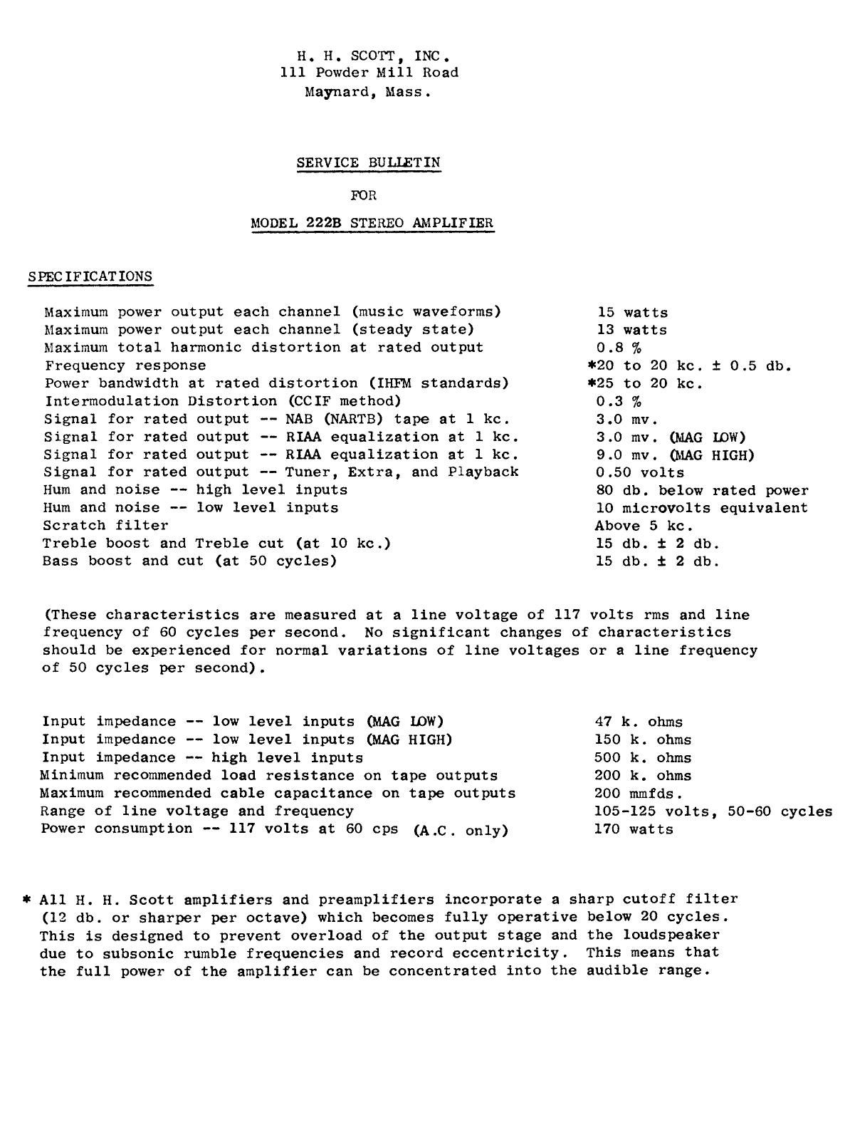
SPECIFICATIONS
Maximum power output each channel (music waveforms) 15 watts
Maximum power output each channel (steady state) 13 watts
Maximum total harmonic distortion at rated output 0.8 %
Frequency response #20 to 20 kc. t 0.5 db.
Power bandwidth at rated distortion (IHFM standards) #25 to 20 kc.
Intermodulation Distortion (CCIF method) 0.3 %
Signal for rated output ~- NAB (NARTB) tape at 1 kc. 3.0 mv.
Signal for rated output -- RIAA equalization at 1 kc. 3.0 mv. (MAG low)
Signal for rated output -- RIAA equalization at l kc. 9.0 mv. OMAG HIGH)
Signal for rated output -- Tuner, Extra, and Playback 0.50 volts
Hum and noise -- high level inputs 80 db. below rated power
Hum and noise -- low level inputs 10 microvolts equivalent
Scratch filter Above 5 kc.
Treble boost and Treble cut (at 10 kc.) 15 db. 1 2 db.
Bass boost and cut (at 50 cycles) 15 db. t 2 db.

(These characteristics are measured at a line voltage of 117 volts rms and line
frequency of 60 cycles per second. No significant changes of characteristics
should be experienced for normal variations of line voltages or a line frequency
of 50 cycles per second).

Input impedance -- low level inputs (MAG 10W) 47 k. ohms

Input impedance -- low level inputs (MAG HIGH) 150 k. ohms

Input impedance -- high level inputs 500 k. ohms

Minimum recommended load resistance on tape outputs 200 k. ohms

Maximum recommended cable capacitance on tape outputs 200 mmfds.

Range of line voltage and frequency 105-125 volts, 50-60 cycles
Power consumption -- 117 volts at 60 cps (A,c, only) 170 watts

* A11 H. H. Scott amplifiers and preamplifiers incorporate a sharp cutoff filter
(12 db. or sharper per octave) which becomes fully operative below 20 cycles.
This is designed to prevent overload of the output stage and the loudspeaker
due to subsonic rumble frequencies and record eccentricity. This means that
the full power of the amplifier can be concentrated into the audible range.

Page 2

GENERAL SERVICE NOTES

1.

Check the tubes, particularly those in the power output stage and

the rectifier every year. If the tubes are outside the manufacturer's
ratings or show gas, they should be replaced. Gassy tubes may damage
other components of the circuit.

When the amplifier is being checked yearly, clean the tubes of dust so
that they may radiate their heat more effectively.

If at any time the hum or noise increases noticeably, check the power
tubes. This symptom is often an indication of gassy tubes.

If the amplifier blows fuses frequently, check the line voltage. If

it rises above 125 volts, drOp the line voltage by means of an auto-
transformer or place a voltage regulator transformer between the ampli-
fier and the line. If the line voltage is correct, check the amplifier
itself. Do not use fuse sizes other than the fuse size specified.

SERVICE PROCEDURE - (Should only be performed by qualified, experienced service

1.

agency, employing adequate test instruments)

Equipment necessary:

Oscilloscope, audio oscillator, VTVM (AC and DC), 16 ohm resistive
load of adequate wattage (some wirewound resistors have considerable
residual inductance and these should be avoided), an adjustable 400
cycle null (schematic for making one of these simple, but extremely
useful devices can be obtained by writing to the Engineering Depart-
ment). For laboratory measurements, a wave analyzer may be necessary.

Instruments wired from kits generally have distortion far too high
for servicing precision electronic components.

Bias adjustment:

Remove bottom plate of amplifier. Place a Dc voltmeter across the

1.2 k resistor (R 201 on schematic) and adjust bias control until
meter reads 38.5 volts. Bias control is located between the electroly-
tic and the power transformer.

D.C. Balance:

The control for each amplifier output stage is 10cated between the
output tubes for that stage. These controls should be adjusted when
the output tubes age appreciably or are replaced. To set these con-
trols use the following procedure:

-2-