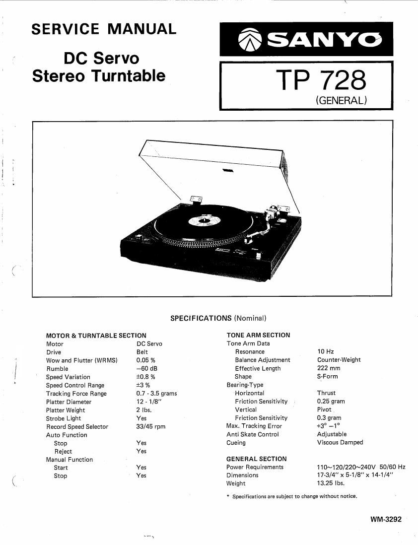
Sanyo TP 728 Service Manual

This is the 12 pages manual for Sanyo TP 728 Service Manual.
Read or download the pdf for free. If you want to contribute, please mail your pdfs to info@audioservicemanuals.com.

Page: 1 / 12
left right
Sanyo TP 728 Service Manual

Extracted text from Sanyo TP 728 Service Manual (Ocr-read)


Page 1

/\

SERVICE MANUAL
DC Servo

is SANYo

Stereo Turntable TP 728
(GENERAL l
SPECIFICATIONS (Nominal)

MOTOR & TURNTABLE SECTION TONE ARM SECTION

Motor DC Servo Tone Arm Data

Drive Belt Resonance 10 Hz

Wow and Flutter (WRMS) 0.05 % Balance Adjustment Counter-Weight

Rumble -60 dB Effective Length 222 mm

Speed Variation $0.8 % Shape S-Form

Speed Control Range :3 % Bearing-Type 7

Tracking Force Range 0.7 - 3.5 grams Horizontal Thrust

Platter Diameter 12 - 1/ Friction Sensitivity . 0.25 gram

Platter Weight 2 lbs. Vertical Pivot

Strobe Light Yes Friction Sensitivity 0.3 gram

Record Speed Selector 33/45 rpm Max. Tracking Error +3° -1°

Auto Function Anti Skate Control Adjustable
Stop Yes Cueing Viscous Damped
Reject Yes

Manual Function GENERAL SECTION
Start Yes Power Requirements 110~120/220~24DV 50/60 HZ
Stop Yes Dimensions 17-3/4" x 54/8" x 14-1/4

Weight 13.25 lbs.

* Specifications are subject to change without notice.

WM-3292

Page 2

BLOCK DIAGRAM OF THE DC SERVO

Principle of Operation

The frequency generator is placed coaxially with the motor shaft. The output signal from the frequency
generator is converted into a rectangular wave in the speed detecting circuit, which is then supplied to the
differentiating circuit to obtain a differentiated wave from synchronized to the frequency of rotation.

The leading edge of the differentiated wave form is used for switching a transistor ON or OFF to obtain a
saw-tooth wave whose wave peak is proportional to the frequency.

The saw-tooth wave thus generated is compared with a reference voltage obtained from a reference voltage
circuit separately composed, and the portion of the sawtooth wave exceeding the reference voltage is taken
out as the control signal.

The driving signal for the motor is obtained by integrating the control signal (rectangular pulse).

Motor speed can be adjusted by changing the reference voltage.

Control frequency:

EP disk motor speed 1520 rpm ...................... 304 Hz

LP disk motor speed 1130 rpm ...................... 226 Hz
Speed detecting _, Differentiating _. Saw-tooth wave Comparator Driving
circuit circuit generating circuit circuit circuit

Reference voltage
circuit

M :MOTOR .
F.G : FREQUENCY GENERATOR
F-G
SPEED ADJUSTMENT

I This unit is built-in F-G- SERVO circuit and the speed has been adjusted accurately in the factory.
0 If, for any reason, when you change the speed, turn these volumes with the screwdriver to the +" direction
or - direction.
+" direction ................ This increases the speed.
"- direction ............... This decreases the speed.

MOTOR F.C.B. SPEED ADJUST VR

@@

- + - +
O 33 RPM 45 RPM O

BOTTOM VIEW

TP 728