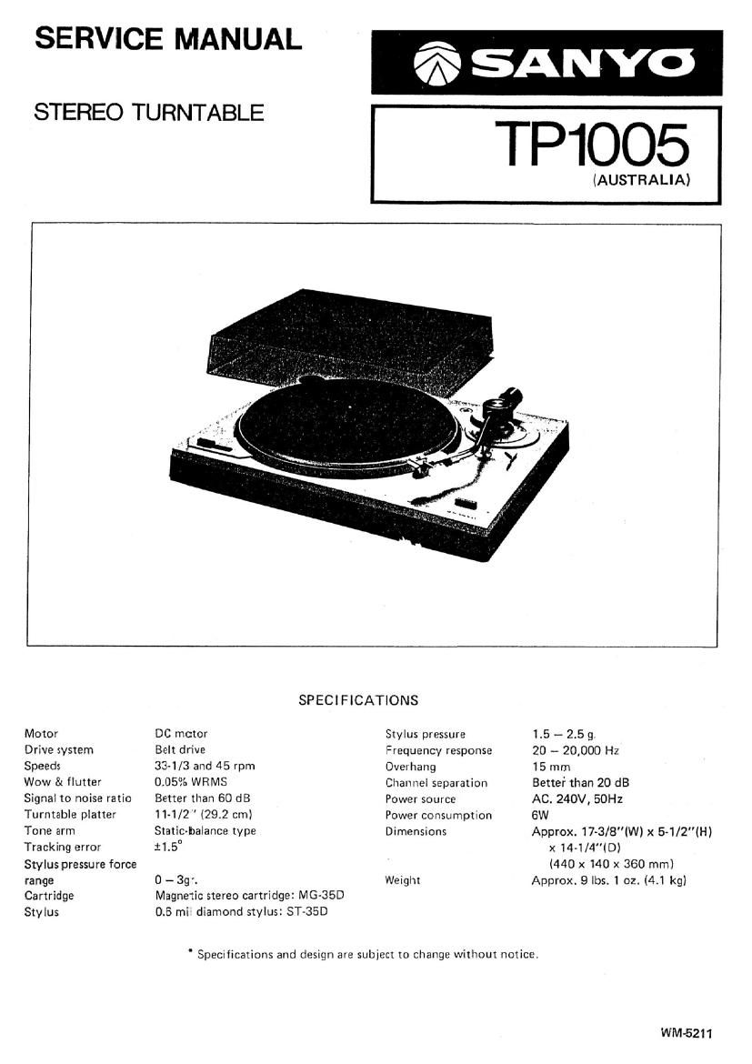
Sanyo TP 1005 Service Manual

This is the 8 pages manual for Sanyo TP 1005 Service Manual.
Read or download the pdf for free. If you want to contribute, please mail your pdfs to info@audioservicemanuals.com.

Page: 1 / 8
left right
Sanyo TP 1005 Service Manual

Extracted text from Sanyo TP 1005 Service Manual (Ocr-read)


Page 1

SERVICE MANUAL

6;; SANYO

(AUSTRALIA)
SPECIFICATIONS
Motor DC motor Stylus pressure 1.5 - 2.5 9.
Drive system Belt drive Frequency response 20 -- 20,000 Hz
Speeds 331/3 and 45 rpm Overhang 15 mm
Wow & flutter 0.05% WRMS Channel separation Better than 20 dB

Signal to noise ratio
Turntable platter
Tone arm

Tracking error
Stylus pressure force
range

Cartridge

Stylus

Better than 60 dB
11-1/2" (29.2 cm)
Static-balance type
:15

0 - 3gr,

Magnetic stereo cartridge: MG-35D
0.5 mil diamond stylus: ST-35D

Power source
Power Consumption
Dimensions

Weight

AC. 240V, 50Hz
6W
Approx. 17~3/8"(W) x 5-1/2(H)
x14-1/4(D)
(440 x140 x 360 mm)
Approx. 9 lbs. I oz. (4.1 kg)

' Specifications and design are subject to change without notice,

WM-5211

Page 2

ADJUSTMENT

ADJUSTMENT 0F TONEARM LEVER
Set the turntable unit upside down after putting the tone~

arm on the arm rest and securing it. Headless screws .
Thém'loosen the set screw (wlhex hole) andaagiirafifia (vii/fie; 0e ,7, , , , ,, ,,

lever (M18) in such a way that the protrusion of the micro-

switch contacts the foremost end of the lever.

ADJUSTMENT 0F MICRO-SWITCH

Set the turntable unit back in its normal position (the
turntable platter at the top). Loosen the round hend screw
(Y7) (see illustration) with a screwdriver and adjust the
'nicroswitch position. so that the micro-switch will be
:urned on when the tonearm has moved a little toward the
turntable center.

The micro-switch should be correctly positioned at a place
where it provides a rotational start for the turntable when
{he tonearm head centers an area 35 through 38cm away
from the center.

ADJUSTMENT OF AUTO-RETURN

l'here is a shaft which is aocessible with an long shaft
1-:rewdriver through the hole below the tonearm. (See
illustration at right.) When the stylus has reached a point
approximately 55mm from the turntable center turn the
:haft clockwise or counter-clockwise and select a position
where it actuates the a'uto-return.

ADJUSTMENT OF HEADSHELL

.'he headshell attached to the tonearm should not be
nclined either to the right or to the.left. if necessary,
oosen the two screws on the bottom of the tubular arm
1nd adjust the headshell. Be sure that the stylus is normal to
.he record surface.

-2-