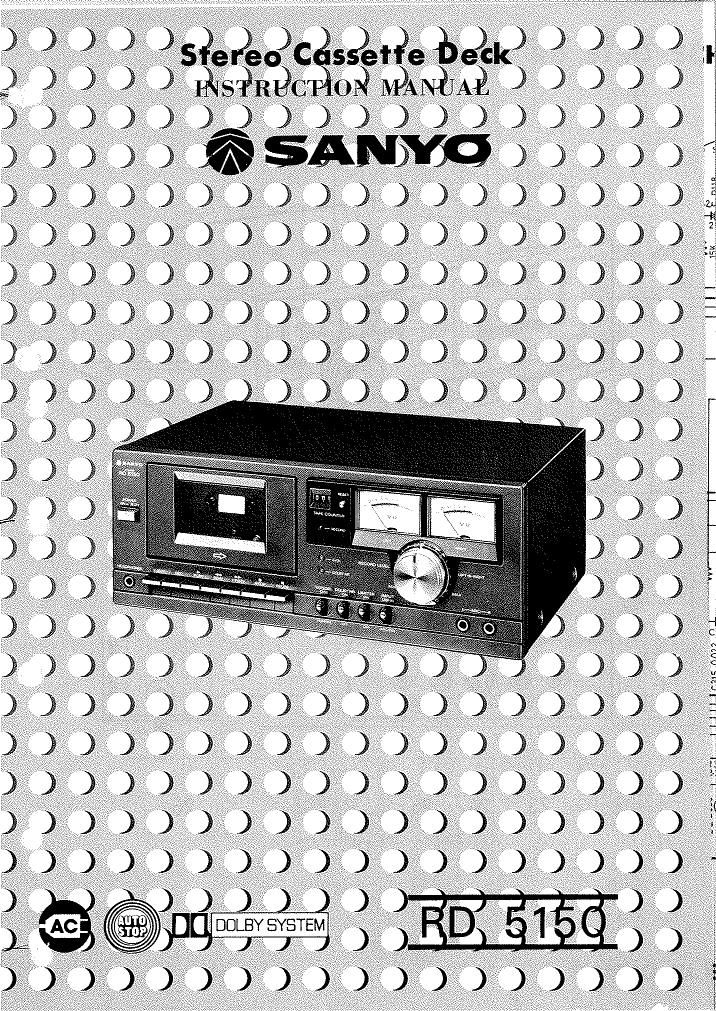
Sanyo RD 5150 Owners Manual

This is the 5 pages manual for Sanyo RD 5150 Owners Manual.
Read or download the pdf for free. If you want to contribute, please mail your pdfs to info@audioservicemanuals.com.

Page: 1 / 5
left right
Sanyo RD 5150 Owners Manual

Extracted text from Sanyo RD 5150 Owners Manual (Ocr-read)


Page 2

CONTROLS

20

1 12 22 2111

@=:@@

R LINE OUT-L REC PLAY R-LINElN-L

26

Fig. 1

_1_

11.
12.
13.

15.

16.

. Cassette compartment lid

Power switch
Turns the unit ON and OFF.

. Headphones socket

Provides for headphone monitoring during
recording or private listening during playback.
Accepts standard phone plug.

. Eject button

Press to eject the cassette.

. Record button

Press the RECORD and PLAY buttons to
activate record circuit and the erase head.

. Play button

Press to start playback.

. Rewind button

Press to rewind the tape quickly.

. Fast forward button

Press to wind the tape forward quickly.

. Stop button

Press to stop the tape travel.

Pause button

Press to momentarily stop the tape travel during
recording and playback.

Cr02 tape indicator lamp

Dolby NR indicator lamp

Tape select switch

Selects proper recording equalization for the
type of tape being used. As switch affects
circuitry in both recording and playback, it must
be set to proper tape type during both operating
modes.

Cr02 ....... Chromium dioxide tape
NORMAL ....... Standard tape
Recommended brand of tapes are . . .
CrOz ....... TDK, Memorex C-60
NORMAL ....... Sanyo, BASF C-60

When the switch is set to 0:02 position the CrOz
tape indicator lamp will light.

. Dolby NR switch

Activates the Dolby System noise-reduction
circuit during recording and playback. Optimum
music recording is achieved by placing the switch
to ON. The Dolby NR indicator lamp will light
up simultaneously.

Limiter switch

Set this switch to ON to record without
distortion caused by high signal peaks.

Input select switch

Provides input selection for optimum input
condition, in MIC/DIN position, the unit records
signals from microphone/DIN (REC/PLAY) and
in LINE IN position, records LINE IN signals.

17.

18.

19.

20.

21.

22.

23.

24.

25.

26.

Microphone input sockets

Separate inputs for left and right channel
microphones provide for stereo live recording.
Record level control knobs

Separate controls provide of independent
adjustment of each channel's recording level for
precise adjusting and balancing of stereo signals.
Level index marker

After adjusting the input levels, set the index
marker to the position where level control knobs
have been set. This marker is useful for repeating
the recording, playing back, and re recording at
the same input level.

VU meters

Illuminated VU meters help to assure optimum
recording levels and indicates relative playback
levels.

Tape counter & reset button

Use this tape counter to find desired position
more quickly.

Record indicator lamp

Line output sockets

Connect to tape monitor or auxiliary inputs of
stereo recorder, amplifier or other stereo record
system. Do not plug into tape head inputs.

DIN (REC/PLAY) socket

Connect to REC/PLAY (DIN) socket of stereo
amplifier or other stereo system. Accepts DIN
type plug.

Line in sockets

Connect the patch cords to these sockets and
other ends to output of tuner, phonograph or
equivalent.

Power cord

Connect attached power cord to AC wall socket.