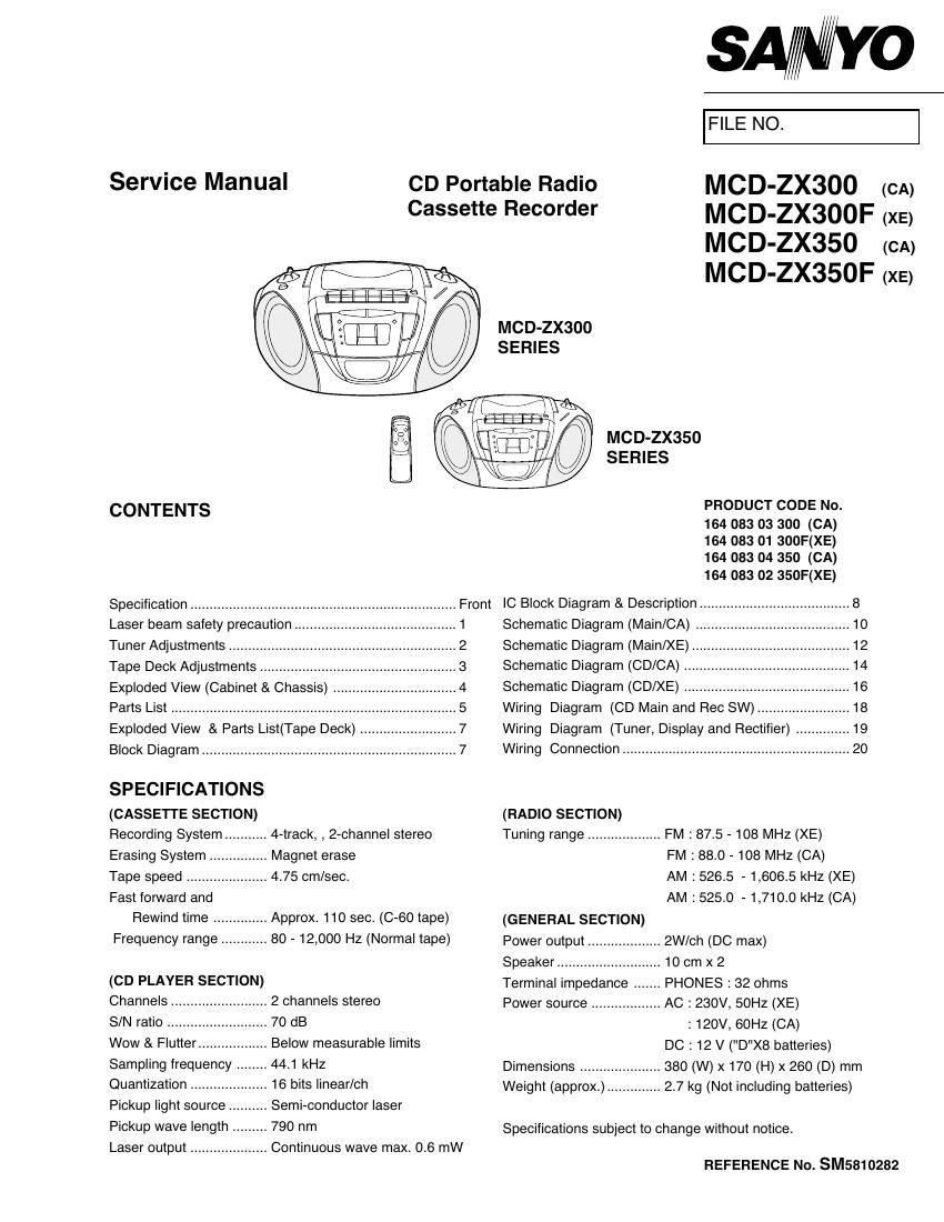
Sanyo mcd zx300 zx350

This is the 18 pages manual for sanyo mcd zx300 zx350.
Read or download the pdf for free. If you want to contribute, please mail your pdfs to info@audioservicemanuals.com.

Page: 1 / 18
left right
sanyo mcd zx300 zx350

Extracted text from sanyo mcd zx300 zx350 (Ocr-read)


Page 1

- 1 - CAUTION : USE OF CONTROLS OR ADJUSTMENTS OR PERFORMANCE OF PROCEDURES OTHER THAN THOSE SPECIFIED HEREIN MAY RESULT IN HAZARDOUS RADIATION EXPOSURE. LASER OUTPUT ................ 0.6 mW Max. (CW) WAVE LENGTH ................. 790 nm IC301 LA4227(Power Amp.) IC201 TA2068N (Cassette Preamp.) + STANDBY SW BIAS CIRCUIT Ch1 Ch2 THERMAL SHUT DOWN PROTECTION - +- 12 34 56 7 8 9 10 11 12 STANDBYOUT2 BS2 NF2 IN2 DC (FILTER) VCC OUT1BS1 NF1 IN1PRE GND IC903 MM1469XH (CD Driver) IC BLOCK DIAGRAM & DESCRIPTION 28 27 26 25 24 23 22 21 20 19 18 17 16 15 1234567 891011 12 13 14 Vcc Vcc DRIVER MUTED. B U F D. B U F D. B U F D. B U F D. B U F D. B U F D. B U F D. B U F Level shift Level shift Level shift Level shift T. S . D - Pickup that emits a laser beam is used on this CD section. LASER BEAM SAFETY PRECAUTION

Page 2

- 2 - T103 T102 JW106 T101 T104IC101 JW105L101 VC102VC103L102VC104VC103 FM ANT FM (E) MW ANT 1. AM ADJUSTMENTBand switch : MW StepAdjusting Connection S GPosition ofAdjust-VTVM CircuitInputOutputFrequencytuning dialment Oscilloscope Closed the output Connect sweep 1IFterminal by sweepgenerator to 465 kHz LowT103 generator , it placeIC101 (19 (H)) and to MW ANT.C107 (E). 2515 kHzLow end T101 Tuning Connect AM SG to Connect VTVM toMax. 3coverageTEST LOOP.speaker terminals.1640 kHzHigh end VC103 4600 kHz 600 kHz MW COIL TrackingConnect AM SG to Connect VTVM toMax. 5TEST LOOP.speaker terminals.1400 kHz 1400 kHz V104 - Use a plastic screw driver for adjustments. - Adjust the intermediate frequency of AM and FM to the frequency of ceramic filter. - Set of unit Supply voltage : DC 12V Speaker : 4 ohms Standard output : 50 mW (450 mV) Function switch : RADIO PARTS LOCATION TUNER ADJUSTMENTS This is a basic adjustment. 2. FM ADJUSTMENTBand switch : FM FM Dummy antenna : 75 ohms unbalance StepAdjusting Connection S GPosition ofAdjust-VTVM CircuitInputOutputFrequencytuning dialment Oscilloscope T104 and 1IF 10.7MHz LowT102 287MHz Low endL102 Tuning Connect FM SG to Connect VTVM toMax. 3coverage FM ANT (H) & FM (E).speaker terminals.109MHz High end VC101 490.0MHz 90.0MHz L101 TrackingConnect FM SG to Connect VTVM toMax. 5FM ANT (H) & FM (E).speaker terminals.106.0MHz 106.0MHzVC102 Connect sweep generator to IC101 (24pin) and C107 (E) Connect VTVM generator to IC101 (19PIN) and C1075 (E).