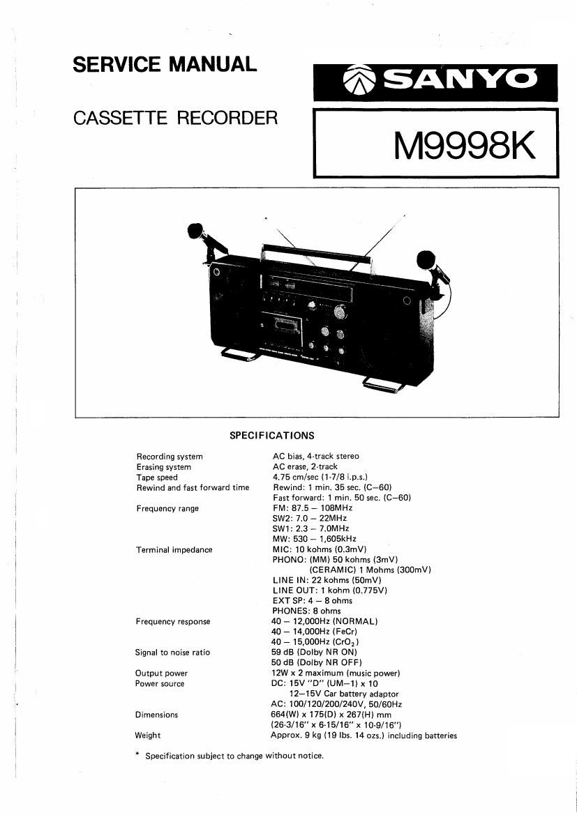
Sanyo m 9998k

This is the 27 pages manual for sanyo m 9998k.
Read or download the pdf for free. If you want to contribute, please mail your pdfs to info@audioservicemanuals.com.

Page: 1 / 27
left right
sanyo m 9998k

Extracted text from sanyo m 9998k (Ocr-read)


Page 2

DlSMOUNTlNG OF CABINET AND CHASSIS

In the first place, take the batteries out of the battery case,
or pull off the power cord

(1) Removing the back lid
Take off 8 screws (pan head tapping screws 3 x 40 mm)
from the back lid (of which two are found in the
battery case).
Open the back lid, with care not to break the leads
inside, Disconnect the lead sockets of the sets PCBs
from the back lid's PCBs.

Back lid side Set side
Beat cancel 2P - A Oscillation PCB
(Brown socket)
Speaker selection 2P - B Front socket PCB
(Gray~hrown socket)
External speaker AP - C Speaker
(Hed-black~brown-orange
socket)
2P - D Amp PCB
(Red-white socket)
Line out 4? - E Amp PCB

(Gray-brown socket)
Rod antenna socket 1Px2 - F Tuner, switch PCB
(Blue«brown socket)
Bandy cord 2? A G Amp PCB
(Brown-white socket)
7P - H Tuner. switch PCB
(Blue-gray-brown»red sock-
et)
Power supply PCB - l AMSS PCB
By removing these 10 sockets, the back lid can be taken off.

(2) Removing the Cabinet

Remove all control knobs and levers. Pick up power
button and battery check/dial light button, and turn
them clockwise and counterclockwise (sketch) respec-
tively, then these buttons will be locked in raised
positions.

Take off 4 red screws (3 pan head tapping screws
3 x 30 mm, 1 pan head tapping screw 3 x 40 mm)
which are joining the chassis and the cabinet together.
Sepearate the microphone socket from the amplifier
PCB, and remove screw 209 (pan head tapping screw
3 x 8 mm) from the oscillation PCB (110). Disconnect
the three sockets of LED PCB (106) from the AMSS
PCB (107).

Lifting the chassis a little, dismount the chassis from
the cabinet. Now, the chassis and the cabinet are
separated from each other.