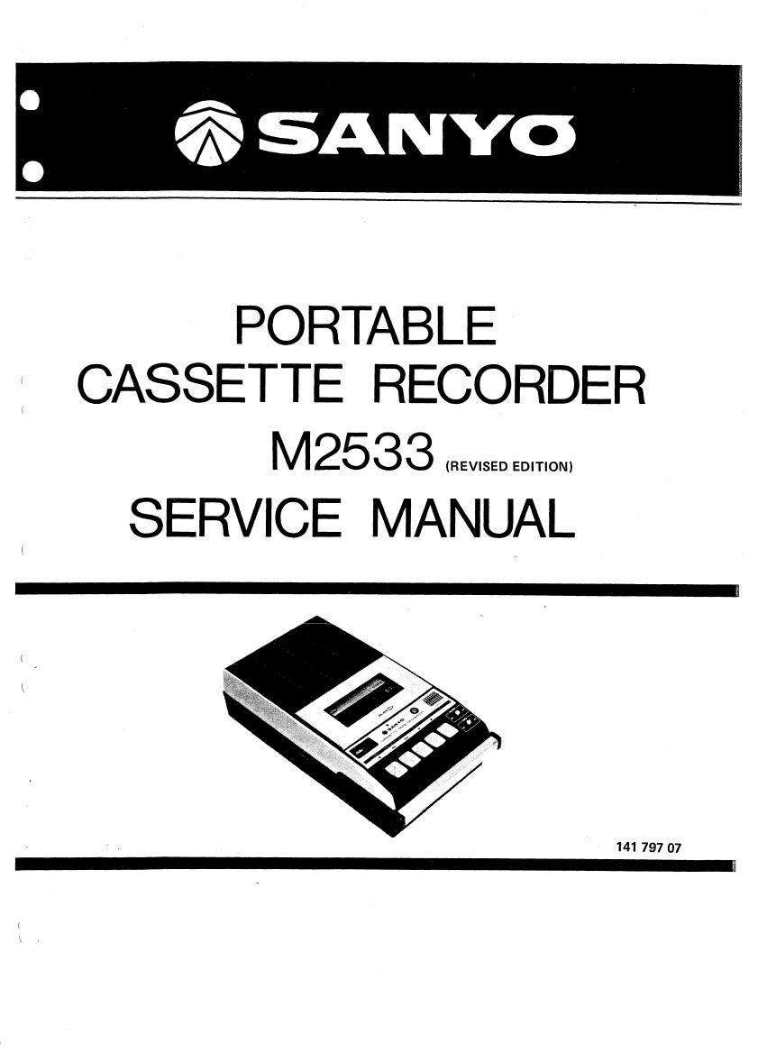
Sanyo m 2533

This is the 12 pages manual for sanyo m 2533.
Read or download the pdf for free. If you want to contribute, please mail your pdfs to info@audioservicemanuals.com.

Page: 1 / 12
left right
sanyo m 2533

Extracted text from sanyo m 2533 (Ocr-read)


Page 1

PORTABLE
CASSETTE RECORDER

M2533 EEEEEEEEEEEEEEEE
SERVICE MANUAL

Page 2

SPECIFICATIONS

Tape Speed 1-7/8 ips. 13%

Fast Forward Time 90 sec. (060 cassette)

Rewind Time 90 sec. (060 cassette)

Wow & Flutter 0.3% RMS.

Terminal Impedance MIC. 4.7 kvohm
DIN INPUT 4.7 kchm
DIN OUTPUT 22 k-ohm
EXT. Speaker 4 ~ 8 ohm

Closstalk Better than 55 dB (track to track)

GENERAL REMAR KS

Before attempting to adjust the mechanism of this
unit, wipe the tape contacting surfaces (of the
sensor, pinch roller, R/P head, Erase head and
capstan) clean as well as the contact surfaces of the
driving parts (the motor pulley, flywheel, take-up
pulley, take~up reel, idler roller, rewind roller and
supply reel) with a piece of soft cloth soaked in
alcohol. Oil and grease stains may cause trouble.
Do not clean the drive belt with alcohol-soaked
fabric because it is specially surface-treated.
Replace the belt with a new one if it is stained with
grease or oil.

FLYWHEEL SUPPORT ADJUSTMENT

1. The clearance between the flywheel support
and the flywheel should be 0.05 -- 0.3mm.

2. Loosen the two fastening screws and put a
screwdriver into the adjusting hole. Then adjust
the flywheel support position by turning it as
illustrated.

move the Fl
ywheel Sup on
Flywheel Support:

0.05 7 0.3mm

Flywheel

move the I n
Flywheel Support Flvwm 5

Chassis

Saewdriver

3. After the adjustment, retighten the fastening
screws and fix them with paint or glue to
prevent them from loosening.

NOTE:
Put the chassis upside down and measure the
clearance correctly.

Signal to Noise ratio Better than 45 dB
Hum & Noise Less than40dB
Output Power 1.5 W (maximum)
Frequency Response 125 N 8,000 Hz
Power Consumption 5.0 W
Current Consumption Play 130mA (at VR min.)
F. Forward 21 OmA
REW. 210mA
-Specifications subject to change without notice.-

PINCH ROLLER ADJUSTMENT

l. The clearance between the pinch roller arm and
the pinch roller stopper should be
0.4-1.5mm with the unit in the playback
mode.

2. If necessary, adjust the clearance by bending
the pinch roller stopper as illustrated.

Pinch Roller


Pinch Roller Arm/J
0.4 - 1.5mm

Pinch Roller Stopper

3. Measure the pinch roller pressure with a spr
gaunn (:nnnl :n ma plauhnnil mndn fn

|
5.. .cwg, .... l

we mew. How

the next procedure:

4. Hook the spring gauge on the pinch roller and
put it away from the capstan. Measure the
pressure at the moment when the pinch roller
comes in contact with the capstan again or the
pinch roller starts revolving. It should be
360 - 4509.

5. If necessary, adjust the pressure by bending the
spring or replace the spring with a new one.

Capstan

Pinch Roller


360 - 4509

Spring
Gauge

HEAD POSITION ADJUSTMENT

After the Erase Head has been replaced or

disassembled, adjust its position following the next

procedures:

1. When the unit is in the playback mode, the
distance from the cassette fixing pins to the
Erase Head should be as follows: