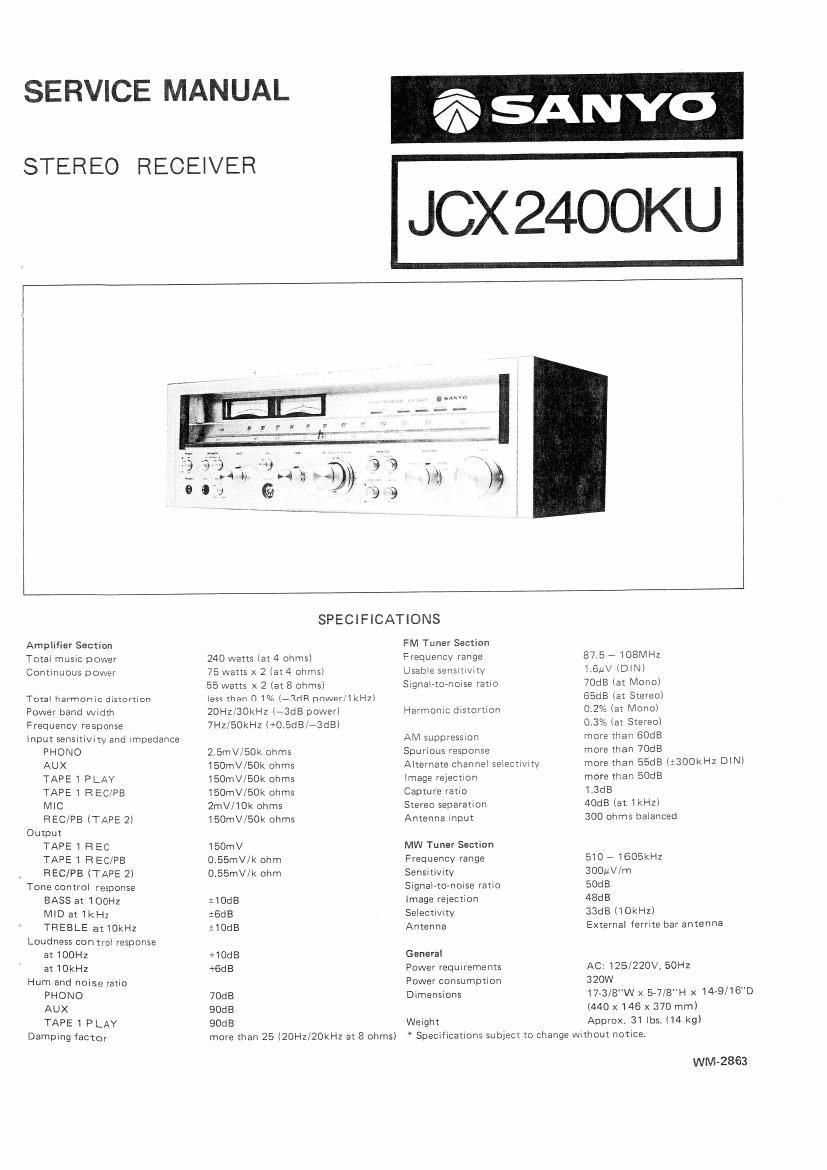
Sanyo jcx 2400ku

This is the 16 pages manual for sanyo jcx 2400ku.
Read or download the pdf for free. If you want to contribute, please mail your pdfs to info@audioservicemanuals.com.

Page: 1 / 16
left right
sanyo jcx 2400ku

Extracted text from sanyo jcx 2400ku (Ocr-read)


Page 2

FM IF ADJUSTMENT
1. V curve adjustment

1) Connect TP3 (HOT) and TP6 (EARTH) to the output
terminal of the sweep generator, and TP4 (H) and
TP104 (E) to the input terminal.

2) Connect a resistance load of about 10 to 50 K-ohms to
the input of the sweep generator and disconnect the
tuning meter leadwires from the circuit board,

3) Cut off ceramic capacitor C213 (0.022pF) at one end.

4) Make adjustment while keeping the output from the
sweep generator at the low level (where noise appears
on the waveform).

5) While watching the sweep waveform, adjust the T201
until the sweep waveform presents the pattern as in
Fig.1.

* TP6is a shield plate.

FMIF Curve

CENTER ADJUSTMENT OF TUNING METER

Set FM SG as follows: modulation frequency 1KHz, frequency
deviation 75KHz DIV. (100% modulation).

Connect a balanced dummy of 300 ohms between FM 86 and
the unit (at the 300 ohm terminal of the external antenna).

1) Set the tuning dial of the unit to 98MHz (where no
Broadcasting signal is coming in)_

2) While keeping the FM SG output level to 0 (less than
10dB), adjust the T202 until the tuning meter needle
stands at the center point.

3) Adjust the frequency output of FM 86 so that the
tuning meter needle stands at the center point.

4) Reduce the distortion factor a minimum by turning the
T203. Make this adjustment at the FM SG output level
of 60 dB (1mV),

2. 8 curve adjustment
1) Connect TP3 (H) and TP6 (E) to the output the sweep
generator. Connect TP201 (H) and TP104 (E) to its input,
NOTE: it is necessary to connecta capacitor (1pF/16V)
to the input of the sweep generator (H) for
cutting DC current.
2) Adjust the T202 until the 8 curve presents the pattern
as in Fig. 2. Avoid turning the T203 unless absolutely
necessary.

FM Detector Curve

5) Repeat steps 2) and 3) above.

5) Turn the core of T201 only slightly untit the distortion
factor becomes minimal.

7) Set the FM SG output level to 0. Confirm tuning meter
needle stands at the center point. If needle is not at
center point, repeat from steps 2).

8) Set the FM SG output level to GOdB. Conform the
distortion factor gets minimum when the tuning meter
needle is at center point.

NOTE: Use Hum and Sub-carrier Filter to get accurate
distortion factor,

mr ritrsn

FM TRACKING
Set FM SG as follows: modulation frequency 1KHZ, frequency
diviation 75KHZ DIV, (100% modulation).
Flip the MODE switch of the unit to MONO.
1) Make LOW TRACKING adjustment by means of L102
and L101. Use 90MHZ FM signal for this purpose.
2) Make HIGH TRACKING adjustment by means of
CT2 and CTI. Use 106MHz FM signal for this purpose.

3) Make complete TRACKING adjustment by repeating
steps (1) and (2).

* When properly adjusted, the distortion factor of the
output from the unit is reduced to a minimum, provided
that the distortion factor of the 56 output is about 3%