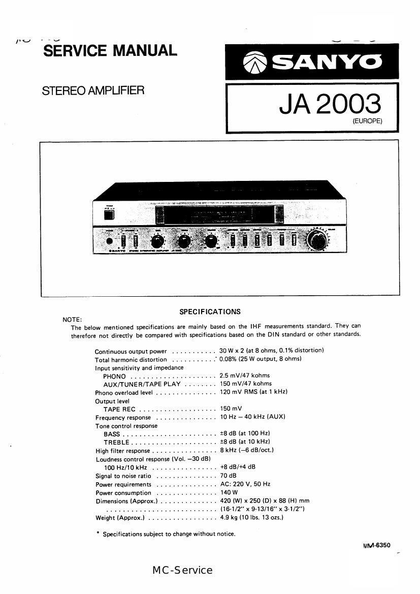
Sanyo ja 2003

This is the 7 pages manual for sanyo ja 2003.
Read or download the pdf for free. If you want to contribute, please mail your pdfs to info@audioservicemanuals.com.

Page: 1 / 7
left right
sanyo ja 2003

Extracted text from sanyo ja 2003 (Ocr-read)


Page 1

IV

SERVICE MANUAL

STEREO AMPUFIER

715 SANYO

JA 2003

(EUROPE)

1

SPECIFICATIONS

The below mentioned specifications are mainly based on the lHF measurements standard. They can
therefore not directly be compared with specifications based on the DIN standard or other standards.

Continuous output power ........... 30 W x 2 (at 8 ohms, 0.1% distortion)
Total harmonic distortion ........... 0.08% (25 W output, 8 ohms)
Input sensitivity and impedance
PHONO ..................... 2.5 mV/47 kohms
AUX/TUNER/TAPE PLAY ........ 150 mV/47 kohms
Phone overload level ............... 120 mV RMS (at 1 kHz)
Output level
TAPE REC ................... 150 mV
Frequency response ............... 10 Hz - 40 kHz (AUX)
Tone control response
BASS ....................... :8 dB (at 100 Hz)
TREBLE ..................... :8 dB (at 10 kHz)
High filter response ................ 8 kHz (-6 dB/oct.)
Loudness controi response (Vol. -30 dB)
100 Hz/10 kHz ................ +8 dB/+4 dB
Signal to noise ratio ............. 70 dB
Power requirements ............... AC: 220 V. 50 Hz
Power consumption ............... 140 W
Dimensions (Aporox.) .............. 420 (W) x 250 (D) x 88 (H) mm
........................... (16-1/2" x 9~13/16"x 3-1/2")
Weight (Approx.) ................. 4.9 kg (10 lbs. 13 ozs.)

" Specifications subject to change without notice.

WM-6350

MC-Service

Page 2

ADJUSTMENT

1. ADJUSTMENT 0F BIAS
' CONDITIONS

VOLUME CONTROL: 0" (Mimimum)
BALANCE CONTROL VOLUME: 0" (Center)
BASS CONTROL VOLUME: 0" (Center)
TREBLE CONTROL VOLUME: "0 (Center)
FUNCTION SWITCH: TUNER
MONITOR SWITCH: SOURCE A
HIGH FILTER SWITCH: OFF
LOUDNESS SWITCH: OFF
SPEAKER SWITCH(A): ON
SPEAKER SWITCH(B): OFF
OUTPUT LOAD: NO LOAD

After the power switch is turned on, adjust SVR701 and

SVRBOI respectively as follows.

L~channelz SVR701 for 2~3mV reading between the
both leads of R716. '

R-channel: SVRBO1 for 2~3mV reading between the
both leads of R8174

2. ADJUSTMENT OF POWER LEVEL METER

* CONDITIONS
INPUT SIGNAL: 1 kHz, 150 mV
OUTPUT LOAD: 8 $2, 100 W, non-inductive resistance
VOLUME CONTROL: "10" (Maximum)

Apply the signal from the test oscillator (1 kHz, 150 mV) as
input to the tuner terminals.
Adjust SVR702 (L-channel) and SVR802 (RAchannel) so
that the power level meter indication becomes 30W when

the speaker (A) output voltage is 30 W (15.5 V).

DIGITAL VOLT METER(DC)

SVR 702

POWER
LEVEL
METER

TEST OSCILLHOH
(OSCILLAYOF & ATTENquR)

DIGITAL VOLT METER(DC)

TLZJ

INPuI

V'IVM

OSCILLDSCOPE

OUTPUT (5P)

SEY

SVR 801

BIAS

SVR 802

POWER

LEVEL

METER