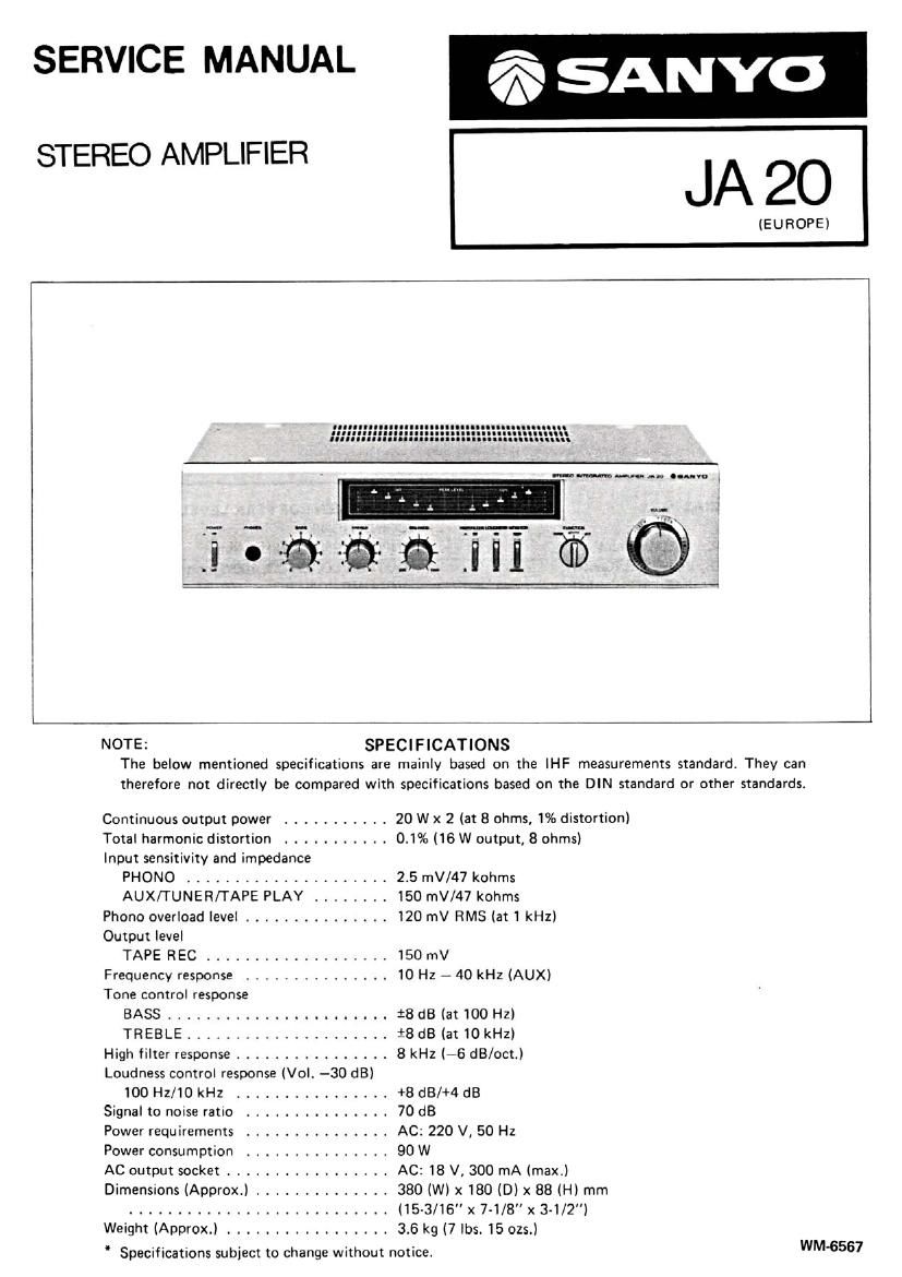
Sanyo JA 20 Service Manual

This is the 6 pages manual for Sanyo JA 20 Service Manual.
Read or download the pdf for free. If you want to contribute, please mail your pdfs to info@audioservicemanuals.com.

Page: 1 / 6
left right
Sanyo JA 20 Service Manual

Extracted text from Sanyo JA 20 Service Manual (Ocr-read)


Page 1

SERVICE MANUAL r3 SANYO

JA 20

STEREO AMPLIFIER

(EUROPE)

:m-
C I
I
I
2:
-
I-II
I
37:0

NOTE: SPECIFICATIONS
The below mentioned specifications are mainly based on the IHF measurements standards They can
therefore not directly be compared with specifications based on the DIN standard or other standards.

Continuous output power ........... 20 W x 2 (at 8 ohms, 1% distortion)
Total harmonic distortion ........... 0.1% (16 W output, 8 ohms)
Input sensitivity and impedance
PHONO ..................... 2.5 mV/47 kohms
AUX/TUNER/TAPE PLAY ........ 150 mV/47 kohms
Phono overload level ............... 120 mV RMS(a1 1 kHz)
Output level
TAPE Fl EC ................... 150 mV
Frequency response ............... 10 Hz -~ 40 kHz (AUX)
Tone control response
BASS ....................... 18 dB (at 100 Hz)
TREBLE ..................... *8 dB (at 10 kHz)
High filter response ................ 8 kHz (-6 dB/oct.)
Loudness control response (Vol. -30 dB)
100 Hz/1O kHz ................ +8 dB/+4 dB
Signal to noise ratio ............... 70 dB
Power requirements ............... AC: 220 V, 50 Hz
Power consumption ............... 90 W
AC output socket ................. AC: 18 V, 300 mA (maxtl
Dimensions lApprox.) .............. 380 (W) x 180 (DIX 88 (H) mm
........................... (15-3/16" x 7-1/8" x 3-1/2")
Weight (Approx.) ................. 3.6 kg (7 lbs. 15 ozs.)

Specifications subject to change without notice. WWI-5567

Page 2

FRONT PANEL DISASSEMBLY

FITTING OF LED METER PCB ASS'Y

J=a

ADJUSTMENT
1. ADJUSTMENT OF BIAS 2. ADJUSTMENT OF PEAK LEVEL METER
uCONDITIONS «CONDITIONS

VOLUME CONTROL: 0" (Minimum)
BALANCE CONTROL VOLUME: (Center)
BASS CONTROL VOLUME: "0" (Center)
TR EBLE CONTROL VOLUME: "0" (Center)
FUNCTION SWITCH: TUNER

MONITOR SWITCH: SOURCE

HIGH FILTER SWITCH: OFF

LOUDNESS SWITCH: OFF

OUTPUT LOAD: N0 LOAD

After the power switch is turned on, adjust SVR703 and
SVR803 respectively as follows:

L - channel: SVR703 for 2~ 3mV reading between the
both leads of R734.

R - channel: SVR803 for 2 ~ 3mV reading between the
both leads of R834.

INPUT SIGNAL: 1kHz, 46mV

OUTPUT LOAD: 80. 100W, non-inductive resistance

VOLUME CONTROL: "10" (Maximum)

(1) Introduce test oscillator signal to the TUNER
terminal.

(2) Adjust test oscillator signal so that LED 3 of the
right side peak level meter begins to light.
(The output voltage of the right side becomes about
3.5V at this time.)

(3) Next, check that the output voltage of left speaker
is same as the right side. Adjust with SVR762 so
that LED 3" of peak level meter begins to light.

TEST OSCILLATOR
(OSCILLAroR I. Arrzuunoa)

VI'VM OSCILLOSCOPE

mvuv ouYPUY (SD)
SE!